WR-G35DDCi Multichannel Coherent Application Guide for Extended topology configuration (ETC)
18
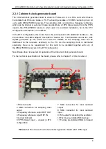
2.3.2 PCIe connector
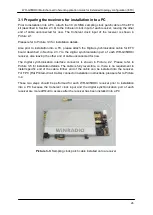
The PCIe connector provides power to the ETC board. As there is no data communication
running through the PCIe connector, no software driver is required for proper operation of
the board. However, the board must be installed into a PCIe slot inside of a PC.
2.3.3 SMA connector SYNC IN
The purpose of the SYNC IN connector is to receive the synchronization signal from the
preceding ETC card in the synchronization chain. Therefore, the SYNC IN connector has to
be connected to the SYNC OUT connector of the preceding ETC board in the synchronization
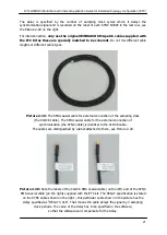
chain. To facilitate this connection, the SMA synchronization coaxial cable (the SYNC cable)
described in Section 2.3.9 is used.
The SYNC IN connector on the first-in-chain board can be left unconnected. Alternatively, it
can be used as the input for the 1PPS signal, when timestamping functionality is required.
The synchronization protocol utilized on this interface is proprietary to WiNRADiO, therefore
no further specification is provided.
2.3.4 SMA connector SYNC OUT
The purpose of the SYNC OUT connector is to transmit the synchronization signal to the
receiver next in the synchronization chain. Therefore, the SYNC OUT connector has to be
connected to SYNC IN connector of the ETC board which follows it in the synchronization
chain. To facilitate this connection, the SMA synchronization coaxial cable (the SYNC cable)
described in Section 2.3.9 is used.
The SYNC OUT connector on the last-in-chain board has to be left unconnected.
The synchronization protocol utilized on this interface is proprietary to WiNRADiO, therefore
no further specification is provided.
2.3.5 Digital synchronization interface
The digital synchronization interface of the ETC board transfers synchronization signals
between the ETC board and the receiver. The digital synchronization cable for the ETC board
(described in Section 2.3.7) attaches to this connector and provides a connection to the
digital synchronization connector of the receiver (described in Section 2.1 and shown in the
Picture 2-2).
The synchronization protocol utilized on this interface is proprietary to WiNRADiO, therefore
no further specification is provided.

