WR-G35DDCi Multichannel Coherent Application Guide for Extended topology configuration (ETC)
21
The delay is specified by the number of sampling clock cycles which it delays the
synchronization signal and is recorded on the label of each SYNC CABLE in the last row, see
the Picture 2-20 on the right.
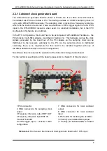
For interconnection,
only use the original WiNRADiO SMA patch cables supplied with
the ETC Kit as these are specially matched to be coherent
. Do not mix different cable
lengths or different cable types.
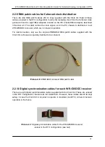
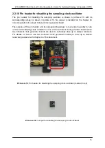
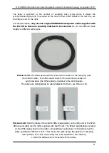
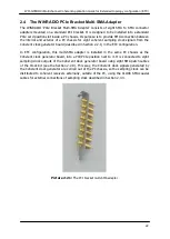
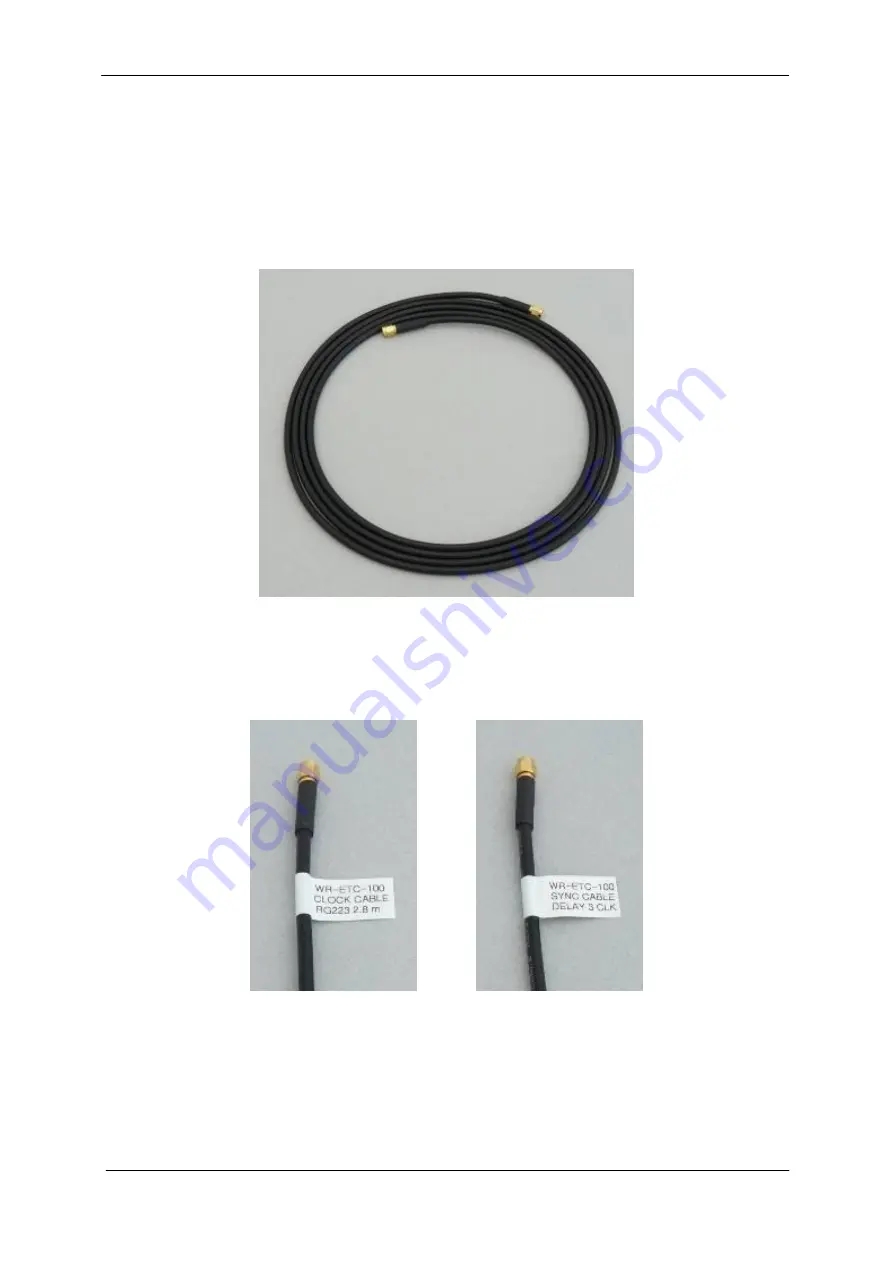
Picture 2-19:
The SMA coaxial cable for external connection of the sampling clock
(the CLOCK cable). The SMA coaxial cable for the external connection of
synchronization (the SYNC cable) is identical to the CLOCK cable.
The cables are distinguished by a label attached to them, see Picture 2-20.
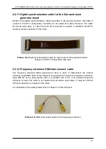
Picture 2-20:
Note the labels of the CLOCK SMA coaxial cable (on the left) and of the SYNC
SMA coaxial cable (on the right) supplied with the ETC kit. The DELAY specification is stated
on the SYNC cable shown on the right – this particular cable shown in the picture has the
delay specified as “DELAY 3 CLK”. That means the cable delays the signal by 3 sampling
clock periods. The value of the delay has to be specified in the software,
so that the software can compensate for the delay.


