WR-G35DDCi Multichannel Coherent Application Guide for Extended topology configuration (ETC)
32
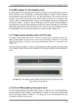
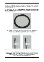
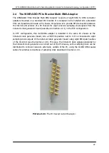
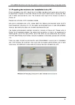
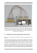
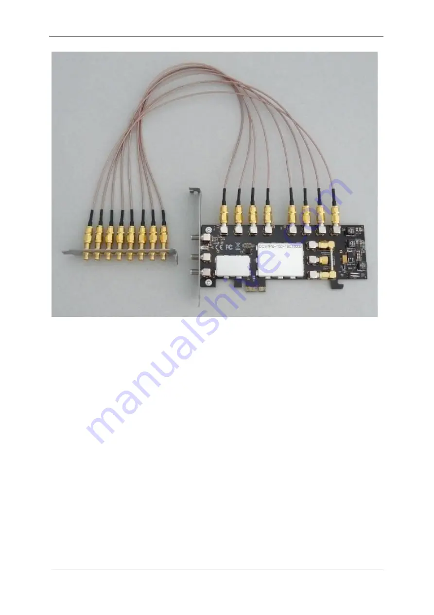
Picture 3-10
: This is an example of interconnection of the Coherent Clock Generator board
of the Clock Kit with the PCIe bracket multi-SMA adapter. Interconnection is made using 45
cm SMA patch cables of the Clock kit. This interconnection is also shown schematically as a
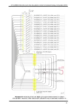
part of Picture 3-1 and Picture 3-2.
3.5 Installing the Coherent clock generator board into the PC
The PC has to be powered off when installing the Coherent clock generator board into a
PCIe slot.
The Coherent clock generator board has to be prepared for installation by interconnecting it
with the PCIe bracket multi-SMA adapter as described in the previous Section. The 1PPS
input and digital synchronization interface of the Clock board are unused in the ETC
configuration, no other preparation to the Clock Board is necessary in the ETC configuration.
The Clock Board has to be installed into a PCIe slot inside of a PC. However, in the ETC
configuration, each WR-G35DDCi receiver is typically installed in a separate dedicated PC,
therefore the complete setup consists of multiple PCs, in each PC the receivers together with
ETC kits are installed. The choice of the PC for the installation of the Clock Board is arbitrary.


