WR-G35DDCi Multichannel Coherent Application Guide for Extended topology configuration (ETC)
38
All cables used for synchronization must have the same delay specified on them. Cables of
various delays cannot be used within one coherent group of receivers.
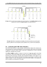
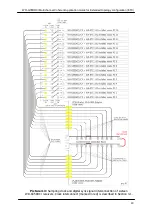
The connection is made in a daisy-chain manner, always linking SYNC OUT of the previous
ETC card with the SYNC IN of next ETC card in the chain (as shown in Picture
3-16).
The first receiver in a chain is called the synchronization master
and is designated as ‘1’ in
the Picture 3-16. The master receiver generates the synchronization signal and sends it
down the synchronization chain. Therefore, the SYNC IN connector on the master receiver is
left unconnected.
The synchronization signal from the master is received by the receiver second in the
synchronization chain
designated as ‘2’ in the Picture 3-16. It is received at its SYNC IN input
of its ETC card. It is then re-sent through its SYNC OUT output and received by
receiver ‘3’
at its SYNC IN input, which also re-sends it through its SYNC OUT to the receiver next in the
chain. This way, the synchronization signals propagate down the synchronization chain from
receiver-to-receiver, and finally to the receiver which is the last in the chain. The receiver
which is the last in chain is
designated as ‘N’ and has its SYNC OUT output left open, as
there is no other receiver which could receive the synchronization signal.
The number of the receivers which can be synchronized is unlimited in theory, but currently it
is limited to 16 by the software. If more than sixteen channels are required, please contact
WiNRADiO.
As mentioned above, the
SYNC CABLES
(described in Section 2.3.4 and 2.3.9).
must be
used
for the SYNC interconnection. All SYNC cables used for synchronization must have the
same delay specified on them. Cables of various delays cannot be mixed within one
coherent group of receivers.
Picture 3-16:
The SYNC interconnection is made in a daisy-chain manner, always linking
SYNC OUT of the previous ETC card with the SYNC IN of next ETC card. The SMA
SYNC
cables
(described in Section 2.3.4 and 2.3.9)
must be used
for the interconnection. The
receivers are not shown in the above picture, only the corresponding ETC cards are shown.


