WR-G35DDCi Multichannel Coherent Application Guide for Extended topology configuration (ETC)
40
4. Extended installation of up to sixteen receivers
To install more than eight and up to sixteen receivers as a single coherent group, two
WiNRADiO Coherence Clock & 1PPS Kits (as described in chapter 2.2, the Clock Kits) as well
as two PCIe Bracket Multi-SMA Adapters (as described in chapter 2.4) are needed. Two
Coherent clock generator boards are interconnected and act as single Coherent clock
generator board, providing 16 outputs of the coherent sampling clock.
The two PCIe Bracket Multi-SMA Adapters provide a way for the Coherent clock signals
(generated by both Coherent clock generator boards) to be carried out of the PC chassis, so
that the sampling clock can be distributed to coherent receivers externally, outside of the PC.
It is strongly recommended that you completely read chapter 3 before continuing to read
this chapter. This chapter (4) covers only the differences between the standard and
extended installations. It is therefore necessary to perform the installation as described in
chapter 3.
4.1 Connecting two Coherent clock generator boards
As mentioned earlier, two Clock Kits are needed to connect from 9 to 16 receivers as a single
coherent group of receivers. In such a configuration, one of the Coherent clock generator
boards acts as master, the other acts as a slave.
The function of the master Coherent clock generator board is exactly the same as in a single
board configuration (as described in 'chapter 3 Installation'). It generates the sampling clock
and distributes it to eight receivers. It also generates the frequency reference if an external
frequency reference is not used. When using an external frequency reference, connect it to
the master Coherent clock generator board only. The 1PPS input and digital synchronization
interface is not used and is left unconnected in the ETC configuration.
On the other hand, the function of the slave Coherent clock generator board is solely to
distribute the sampling clock to the receivers, the sampling clock is not generated on the
slave board. The sampling clock is only generated on the master board and is then fed to the
slave board, which then distributes it to the other eight receivers.
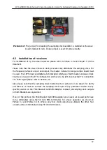
The sampling clock
oscillator has to be turned off on the slave board to prevent interference
. This is
done by installing the jumper onto the pin header used for disabling the sampling clock
oscillator. Both the pin header for disabling the sampling clock oscillator and the jumper are
described in Section 2.2.16 and shown in pictures 2-13 and 2-14. The installed jumper is
shown in picture 4-2.
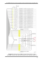
A hook up diagram for two Coherent clock generator boards is shown in Picture 4-1. Use the
SMA patch cables for Coherent clock distribution as described in Section 2.2.9 to
interconnect both boards. Please note that the same cable as used to interconnect the
master and slave boards needs to be used to interconnect the sampling clock output to the
sampling clock input on a master board. Also 50 ohm terminators are needed on the slave
board frequency reference output, frequency reference input and 1PPS input. The sampling
clock oscillator outputs on a slave board can be left unconnected.

