WR-G35DDCi Multichannel Coherent Application Guide for Extended topology configuration (ETC)
41
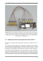
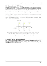
Both Coherent Clock Generator Boards have to be interconnected, each with its respective
PCIe bracket multi-SMA adapter as described in Section 3.4. Such a connection of sixteen
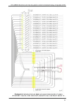
channels is also shown schematically as a part of connection diagram in the Picture 4-3. This
way sixteen coherent SMA clock outputs are provided at the rear of the PC where the Clock
Boards are installed.
All sixteen sampling clock outputs connected to PCIe Brackets multi-SMA Adapters are
equivalent; therefore, any receiver within a coherent group can be connected to any of these
SMA connectors on both Adapters. However, any unused ports have to be terminated using
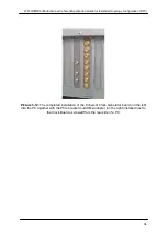
the 50 ohm SMA terminators for proper operation as shown in the Picture 3-15.
). In this
picture only four clock outputs are utilized, while the other four unused ports are terminated
using 50 ohm terminators.
Picture 4-1:
Interconnecting sampling clocks of two Coherent clock generator boards

