WR-G35DDCi Multichannel Coherent Application Guide for Extended topology configuration (ETC)
5
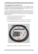
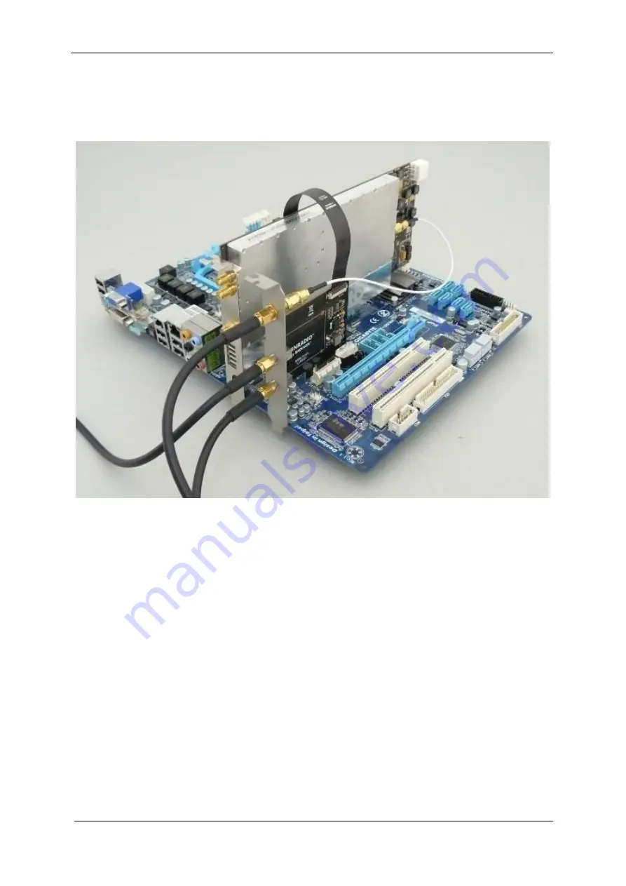
An example of a one receiver, forming part of a multichannel coherent system in ETC
configuration is shown in Picture 1-2.
Picture 1-2:
An example of a one WR-G35DDCi receiver, forming part of a multichannel
coherent system in ETC configuration with the ETC kit, installed into a PC (PC chassis and
other PC connections omitted for clarity). The WR-CC1PPS-100 kit is also required for
coherent operation, but is not shown in this picture.
The coaxial cables (shown in the picture) which are connected to the ETC kit carry the
sampling clock from the WR-CC1PPS-100 kit as well as the digital synchronization signals
needed to coherently synchronize all of the receivers together. The synchronization signals
are connected in a daisy chain manner; thus, two coaxial cables are needed to connect this
particular receiver to its two neighbouring receivers.

