WR-G35DDCi Multichannel Coherent Application Guide for Extended topology configuration (ETC)
9
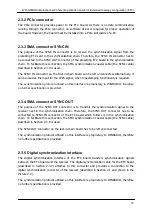
2.2.2 PCIe connector
The PCIe connector provides power to the Coherent clock generator board. As there is no
data communication running through the PCIe connector, no software driver is required for
proper operation of the board. However, the board must be installed into a PCIe slot inside of
a PC.
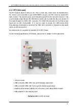
2.2.3 SMA connectors for sampling clock output
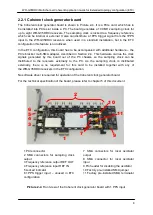
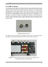
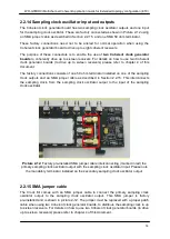
There are eight SMA connectors for the sampling clock output provided on the Coherent
clock generator board. These are located on the top of the board and are facing upwards.
Each WR-G35DDCi receiver within a coherent group must be connected to one of these
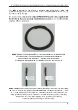
ports using the SMA patch cables (for Coherent clock distribution) supplied with the Clock Kit
and described in Section 2.2.9. All ports are equivalent; therefore, any receiver within a
coherent group can be connected to any of these ports. However, unused ports have to be
terminated using the 50 ohm SMA terminators for proper operation.
Because the sampling clock is distributed externally to the PC in the ETC configuration,
extra hardware is needed to carry the clock signals out of the PC chassis. The PCIe bracket
multi-SMA adapter described in chapter 2.4.
For the technical specification of the sampling clock output signal, please refer to Chapter 5.
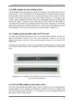
2.2.4 Digital synchronization interface
The digital synchronization interface is located on the rear side of the board. It is unused in
the ETC configuration and has to be left unconnected when operating in the ETC
configuration.
Picture 2-5:
Rear view of the Coherent clock generator board showing the location
of the digital synchronization interface marked in red – it is unused and has to be left
unconnected in the ETC configuration

