WR-G35DDCi Multichannel Coherent Application Guide for Extended topology configuration (ETC)
23
3. ETC installation of up to eight receivers
The basic setup of up to eight receivers in the ETC configuration is shown in Picture 3-1,
although only four receivers are shown in the picture for the picture clarity. A simplified
version of an eight channel setup is shown in the Picture 3-2.
The setup consists of a minimum two and up to eight WR-G35DDCi receivers, each installed
into a PCIe slot inside separate PCs. Each receiver must be accompanied by its own
dedicated ETC kit (described in Section 2.3) installed into a PCIe slot of the same PC as the
particular receiver. In other words, the number of ETC kits needed is equal to the number of
receivers installed. The ETC kit allows for the external interconnections needed for coherent
operation in the ETC configuration.
As mentioned above, in the ETC configuration, each WR-G35DDCi receiver is typically
installed in a separate dedicated PC. Installation of multiple receivers inside the same PC is
allowed in the ETC configuration, however each receiver has to be accompanied with its own
dedicated ETC card. Also, the receivers installed inside the same PC act the same way, as if
they were installed in separate dedicated PCs. In other words, all interconnections have to
be done externally through the ETC board and each receiver has to run its own instance of
software. Also, it is not possible to mix the ETC installation (i.e. external interconnections,
described in this document) with the standard installation (i.e. internal interconnections,
described in another document). All interconnections have to be done externally through the
ETC board, outside of the PC, even if two or more receivers are installed in the same PC.
Another part of the setup is the Coherent clock Generator Board of the Clock Kit (described
in Section 2.2), which generates eight coherent sampling clock signals for the receivers. The
Clock Board has to be installed into a PCIe slot inside of a PC. The choice of the PC for the
installation of the Clock Board is arbitrary. There is no requirement for the Clock Board to be
installed in a specific PC. It can be installed into a PC together with any receiver it feeds, but
doesn’t have to be installed together with any receiver at all. It can (but doesn’t have to) be
installed in separate PC, if desired.
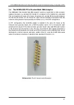
The Coherent clock Generator Board must be accompanied by the
‘PCIe bracket multi-SMA
adapter
’ described in Section 2.4 (and therefore installed inside the same PC), which allows
for external interconnections of the coherent sampling clock signals generated by the
Coherent clock Generator Board.
The receivers and the Coherent Clock Generator Board are interconnected using two types
of cables
– the CLOCK cable and the SYNC cable (described in Section 2.3.9).
The CLOCK cables distribute the sampling clock and connect between the Coherent Clock
Generator Board and each receiver. The SYNC cables distribute the synchronization signals
needed to synchronize the receivers for coherent operation and are connected between
neighbouring receivers in a daisy-chain like manner. The receiver connected first in the
synchronization chain (shown installed in PC1 in Picture 3-1) generates the synchronization
signals and is called the synchronization master (SYNC MASTER). The other receivers
receive and re-transmit the synchronization signals and are called synchronization slaves
(SYNC SLAVE).


