WR-G35DDCi Multichannel Coherent Application Guide for Extended topology configuration (ETC)
26
3.1 Preparing the receivers for installation into a PC
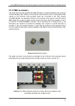
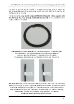
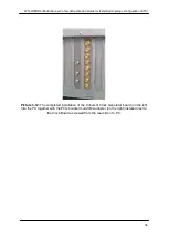
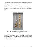
Prior to installation into a PC, attach the 30 cm SMA sampling clock patch cable of the ETC
kit (described in Section 2.3.8) to the Coherent clock input of each receiver, leaving the other
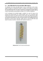
end of cable unconnected for now. The Coherent clock input of the receiver is shown in
Picture 2-1.
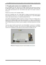
Please refer to Picture 3-3 for installation details.
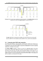
Also prior to installation into a PC, please attach the Digital synchronization cable for ETC
board described in Section 2.3.7 to the digital synchronization port of each WR-G35DDCi
receiver, also leaving the other end of cable unconnected for now.
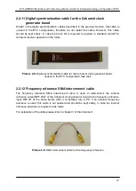
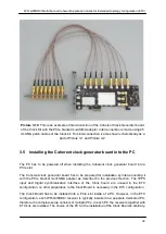
The digital synchronization interface connector is shown in Picture 2-2. Please refer to
Picture 3-5 for installation details. The cable is fully reversible, i.e. there is no requirement to
install specific end of the cable. Either end of the cable can be installed into the receiver.
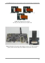
For FPC (Flat Printed-circuit Cable) connector installation instructions, please refer to Picture
3-4.
These two steps should be performed for each WR-G35DDCi receiver prior to installation
into a PC because the Coherent clock input and the digital synchronization port of each
receiver are more difficult to access after the receiver has been installed into a PC.
Picture 3-3:
Sampling clock patch cable installed onto a receiver

