WR-G35DDCi Multichannel Coherent Application Guide for Extended topology configuration (ETC)
28
3.2 Installing the receiver into a PC
A PC has to be powered off when installing the receiver into a PCIe slot.
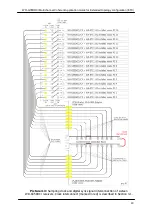
Each receiver has to be prepared for installation as discussed in Section 3.1.
As mentioned earlier, in the ETC configuration, each WR-G35DDCi receiver is typically
installed in a separate dedicated PC. Each receiver must be accompanied with its own
dedicated ETC card. Therefore, two PCIe slots are needed for installation of each receiver
–
one PCIe slot for the receiver and one PCIe slot for the ETC card. The ETC card is typically
installed into a slot next to the receiver and is described in next Section 3.3.
Installation of multiple receivers inside the same PC is allowed in the ETC configuration,
however each receiver has to be accompanied with its own dedicated ETC card. Therefore,
the number of PCIe slots required for the installation is twice the number of receivers
installed.
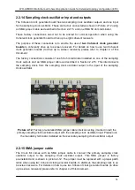
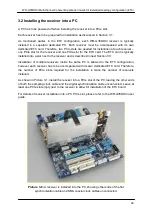
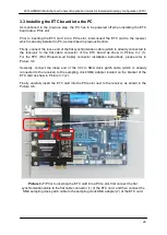
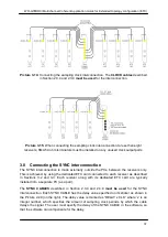
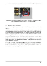
As shown in Picture 3-1, install the receiver into a PCIe slot of the PC, leaving the other ends
of both the sampling clock cable and the digital synchronization cable unconnected. Leave at
least one PCIe slot empty next to the receiver to allow for installation of the ETC board.
For details of receiver installation into a PC PCIe slot, please refer to the WR-G35DDCi user
guide.
Picture 3-6:
A receiver is installed into the PC, showing other ends of the flat
synchronization cable and SMA coaxial clock cables unconnected.

