WR-G35DDCi Multichannel Coherent Application Guide for Extended topology configuration (ETC)
29
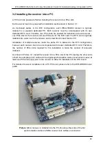
3.3 Installing the ETC board into the PC
As mentioned in the previous step, the PC has to be powered off when installing the ETC
board into a PCIe slot.
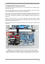
Prior to inserting the ETC card into a PCIe slot, interconnect the ETC card to the receiver
which is already installed in PC, as described in previous Section.
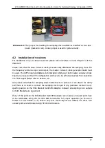
Firstly, connect the loose end of the flat synchronization cable (which is already connected to
the receiver) to the flat cable connector of the ETC board as show in Picture 3-7 (1).
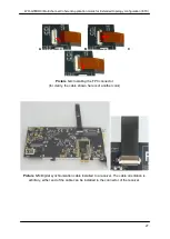
For the FPC (Flat Printed-circuit Cable) connector installation instructions, please refer to
Picture 3-4.
Secondly, connect the loose end of the 30 cm SMA clock patch cable (which is already
connected to the receiver) to the sampling clock SMA adapter located on the bracket of the
ETC card as show in Picture 3-7 (2).
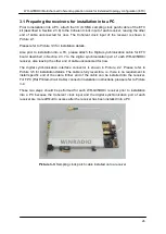
Finally, carefully insert the ETC card into the PCIe slot next to the receiver, as shown in the
Picture 3-8.
Picture 3-7:
Prior to inserting the ETC card into a PCIe slot, first connect the flat
synchronization cable to the flat cable connector (1) of the ETC card, and then connect the
SMA sampling clock patch cable to the sampling clock SMA adapter (2) of the ETC card.
1
2

