WR-G35DDCi Multichannel Coherent Application Guide for Extended topology configuration (ETC)
36
3.7 Connecting the CLOCK interconnection
The CLOCK interconnection is made externally, outside the PCs, between the Clock Board
described in Section 2.2.1 and each receiver.
At the Clock Board side, this connection is made through the dedicated PCIe Bracket
multi-SMA Adapter connected to the Clock Board as described in Section 3.4. The Clock
Board with its dedicated PCIe Bracket multi-SMA can be installed in any PC as described in
Section 3.5.
At the receiver side, this connection is made through the dedicated ETC card connected to
each receiver as described in Sections 3-2 and 3-3. Each receiver with its dedicated ETC
card is typically installed in a separate PC.
The
CLOCK CABLES
(described in Sections 2.3.4 and 2.3.9)
must be used
for the CLOCK
interconnection. Each CLOCK CABLE has the type and length specified on its sticker as
shown in the Picture 2-20 on the left. All cables used for clock distribution must be of the
same type and length. Cables of various types and lengths cannot be used within one
coherent group of receivers. For interconnection,
only use the original WiNRADiO SMA
CLOCK cables supplied with the Clock Kit
as these are specially matched to be coherent.
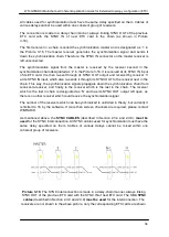
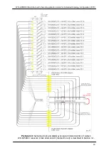
The connection is made in a star-like manner, always linking one of the clock outputs of the
Clock Board (through the PCIe Bracket multi-SMA adapter) with one clock input of the
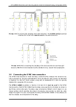
receiver on the ETC card connected to it as shown in Picture 3-14.
All receivers within one coherent group are equal from the clock distribution point of view.
The number of the receivers which can be coherently clocked by one Clock Board is up to
eight. Two Clock Boards can be linked for driving up to sixteen receivers as described in
Chapter 4. If more than sixteen channels are required, please contact WiNRADiO.
As mentioned above, the
CLOCK CABLES
(described in Sections 2.3.4 and 2.3.9)
must be
used
for the CLOCK interconnection. All CLOCK cables used for synchronization must have
the same delay specified on them. Cables of various delays cannot be mixed within one
coherent group of receivers.
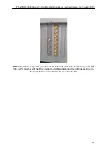
Also please note that the sampling clock interconnects in picture 3-14 are drawn for clarity
and there is no need to connect the sampling clock input of any particular receiver to any
specific position on the PCIe Bracket multi-SMA Adapter. Instead; all sampling clock outputs
on the PCIe Bracket multi-SMA adapter are equivalent. If any of the ports on the PCIe
Bracket multi-SMA adapter are unused, all unused ports have to be terminated using the
50 ohm SMA terminators for proper operation (as shown in Picture 3-15). In this picture only
four clock outputs are utilized, while the other four unused ports are terminated using
50 ohm terminators.

