background image

WR-G35DDCi Multichannel Coherent Application Guide for Extended topology configuration (ETC) 


44


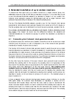
5. Technical specification 


Output sampling frequency


100 MHz  

Sampling clock output level


+2 dBm min. into 50 ohm 

Number of sampling clock output ports


Reference frequency


10 MHz 

REF IN input impedance


50 ohm 

REF IN input level


+2 dBm min. 

REF IN frequency tolerance  


+/- 20 ppm 

REF OUT output level


+4 dBm typ.  into 50 ohm 

Internal frequency reference stability


0.5 ppm 

1PPS input impedance


50 ohm 

1PPS input level L 


0   

–  0.8 V 


1PPS input level H


2.1 V  

–  5 V   


Summary of Contents for WR-ETC-100

Page 1: ...WiNRADiO WR ETC 100 for the G35DDCi Multichannel Coherent Application Guide for the Extended Topology Configuration option ETC Version 1 0...

Page 2: ...igger input 10 2 2 8 Locked indicator 10 2 2 9 SMA patch cables for Coherent clock distribution 11 2 2 10 Digital synchronization cables for each WR G35DDCi receiver 11 2 2 11 Digital synchronization...

Page 3: ...into a PC 26 3 2 Installing the receiver into a PC 28 3 3 Installing the ETC board into the PC 29 3 4 Interconnecting the Coherent Clock Generator board 31 3 5 Installing the Coherent clock generator...

Page 4: ...ETC installation All necessary connections between the receivers and other supportive hardware are realized externally outside of the PCs To couple up to eight receivers the WR CC1PPS 100 WiNRADiO WR...

Page 5: ...a PC PC chassis and other PC connections omitted for clarity The WR CC1PPS 100 kit is also required for coherent operation but is not shown in this picture The coaxial cables shown in the picture whi...

Page 6: ...nt system 2 1 WR G35DDCi connectors The connectors required for coherent operation of the WR G35DDCi receivers are shown in Pictures 2 1 and 2 2 present when the CR option has been fitted Picture 2 1...

Page 7: ...Clock Kit consists of the following components shown in Picture 2 3 1 Coherent clock generator board with 1PPS input 2 SMA patch cables for Coherent clock distribution 9 pcs 3 Digital synchronization...

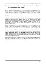
Page 8: ...ock signals generated by this board out of the PC chassis so the sampling clock can be distributed to the receivers externally to the PC As the sampling clock is distributed externally there is no req...

Page 9: ...d described in Section 2 2 9 All ports are equivalent therefore any receiver within a coherent group can be connected to any of these ports However unused ports have to be terminated using the 50 ohm...

Page 10: ...equency reference input REF IN serves as a frequency reference for the 100 MHz sampling clock generator It is a 50 ohm terminated SMA connector A 10 MHz reference signal must be provided on this input...

Page 11: ...G35DDCi receivers which are in coherent operation For interconnection only use the original WiNRADiO SMA patch cables supplied with the Clock Kit as these are specially matched to be coherent Picture...

Page 12: ...igital synchronization cable for the Coherent clock generator board unused in the ETC configuration see text 2 2 12 Frequency reference SMA interconnect cable The frequency reference SMA interconnect...

Page 13: ...have terminators installed on them A minimum of two WR G35DDCi receivers can be connected as a coherent pair so six terminators are needed to terminate the sampling clock outputs A seventh terminator...

Page 14: ...s consists of one 50 ohm terminator installed on one of the sampling clock outputs and an SMA jumper cable as described in Section 2 2 15 This interconnects the sampling clock from the sampling clock...

Page 15: ...generator board The purpose of the pin header and its corresponding jumper is to provide the ability to turn off the local sampling clock oscillator on one of the Coherent clock generator boards when...

Page 16: ...from the Digital synchronization connector of the WR G35DDCi described in Section 2 1 and shown in the Picture 2 2 into signals carried over standard 50 ohm coaxial SMA cables This enables the receive...

Page 17: ...UT connector The SYNC IN connector on the first in chain board can be left unconnected or it can be used to supply the 1PPS signal when time stamping functionality is required The SYNC OUT connector o...

Page 18: ...ietary to WiNRADiO therefore no further specification is provided 2 3 4 SMA connector SYNC OUT The purpose of the SYNC OUT connector is to transmit the synchronization signal to the receiver next in t...

Page 19: ...MA adapter to the Coherent clock input of the receiver shown in Picture 2 1 2 3 7 Digital synchronization cable for ETC board The digital synchronization flat cable for the ETC board provides connecti...

Page 20: ...the right and is used to link the receivers in a daisy chain like manner to synchronize the receivers for coherent operation Each SYNC CABLE has the delay value specified on its sticker The delay val...

Page 21: ...le for external connection of the sampling clock the CLOCK cable The SMA coaxial cable for the external connection of synchronization the SYNC cable is identical to the CLOCK cable The cables are dist...

Page 22: ...r board described in Section 2 2 1 in the ETC configuration In ETC configuration this multi SMA adapter is installed in the same PC chassis as the Coherent clock generator board into a PCI PCIe positi...

Page 23: ...interconnections have to be done externally through the ETC board outside of the PC even if two or more receivers are installed in the same PC Another part of the setup is the Coherent clock Generato...

Page 24: ...DCi Multichannel Coherent Application Guide for Extended topology configuration ETC 24 Picture 3 1 Sampling clock and digital sync signal interconnection of four WR G35DDCi CR receivers in ETC configu...

Page 25: ...t Application Guide for Extended topology configuration ETC 25 Picture 3 2 Sampling clock and synchronization interconnection of eight WR G35DDCi CR receivers in ETC configuration Channels 3 to 7 are...

Page 26: ...digital synchronization port of each WR G35DDCi receiver also leaving the other end of cable unconnected for now The digital synchronization interface connector is shown in Picture 2 2 Please refer t...

Page 27: ...on ETC 27 A B C Picture 3 4 Installing the FPC connector for clarity the cable shown here is of another color Picture 3 5 Digital synchronization cable installed to a receiver The cable orientation is...

Page 28: ...t next to the receiver and is described in next Section 3 3 Installation of multiple receivers inside the same PC is allowed in the ETC configuration however each receiver has to be accompanied with i...

Page 29: ...connector of the ETC board as show in Picture 3 7 1 For the FPC Flat Printed circuit Cable connector installation instructions please refer to Picture 3 4 Secondly connect the loose end of the 30 cm S...

Page 30: ...configuration ETC 30 Picture 3 8 The completed installation of the ETC board into the PC next to the receiver Picture 3 9 The completed installation of the receiver shown on the left and the ETC boar...

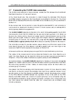
Page 31: ...e PC The CLOCK SMA coaxial cables are used for the external connections of the sampling clock described in Section 2 3 4 There is no need to connect any particular sampling clock output of the Clock B...

Page 32: ...d into a PCIe slot The Coherent clock generator board has to be prepared for installation by interconnecting it with the PCIe bracket multi SMA adapter as described in the previous Section The 1PPS in...

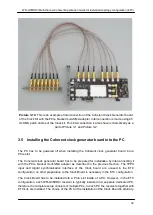
Page 33: ...rt by installing the Clock Board into a PCIe slot of the PC Next install the PCIe Bracket multi SMA adapter into a position next to the Clock Board As the PCIe bracket multi SMA interface is a passive...

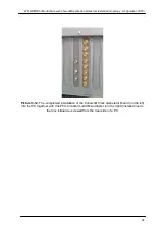
Page 34: ...topology configuration ETC 34 Picture 3 12 The completed installation of the Coherent Clock Generator board on the left into the PC together with the PCIe bracket multi SMA adapter on the right instal...

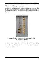
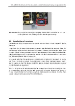
Page 35: ...ter it has been installed into a PC as shown in Picture 3 13 Please use the Frequency reference SMA interconnect cable as described in Section 2 2 12 Picture 3 13 Installing the frequency reference SM...

Page 36: ...de in a star like manner always linking one of the clock outputs of the Clock Board through the PCIe Bracket multi SMA adapter with one clock input of the receiver on the ETC card connected to it as s...

Page 37: ...tween the receivers only This is achieved by using the dedicated ETC card connected to each receiver as described in Sections 3 2 and 3 3 Each receiver along with its dedicated ETC card are typically...

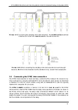
Page 38: ...ends it through its SYNC OUT to the receiver next in the chain This way the synchronization signals propagate down the synchronization chain from receiver to receiver and finally to the receiver which...

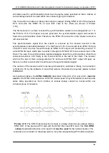
Page 39: ...he 1PPS signal at all If the 1PPS signal is not used the SYNC IN input on the ETC card connected to the master receiver can be left unconnected For the technical specification of the SYNC IN input req...

Page 40: ...3 Installation It generates the sampling clock and distributes it to eight receivers It also generates the frequency reference if an external frequency reference is not used When using an external fre...

Page 41: ...ded at the rear of the PC where the Clock Boards are installed All sixteen sampling clock outputs connected to PCIe Brackets multi SMA Adapters are equivalent therefore any receiver within a coherent...

Page 42: ...nization interface of both master and slave Clock board are unused in the ETC configuration and have to be left unconnected For connection of a 1PPS signal please refer to Section 3 9 Also please note...

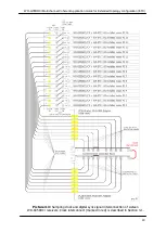
Page 43: ...erent Application Guide for Extended topology configuration ETC 43 Picture 4 3 Sampling clock and digital sync signal interconnection of sixteen WR G35DDCi receivers Clock interconnect marked in red i...

Page 44: ...output level 2 dBm min into 50 ohm Number of sampling clock output ports 8 Reference frequency 10 MHz REF IN input impedance 50 ohm REF IN input level 2 dBm min REF IN frequency tolerance 20 ppm REF O...

Page 45: ...any comments questions or suggestions please use our general enquiry form at www winradio com enquiry Published by Radixon Group Pty Ltd 45 47 Islington Street Collingwood Victoria 3066 Australia 202...

Page 46: ...WiNRADiO C O M M U N I C A T I O N S w w w w i n r a d i o c o m...

Reviews: