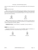
COM2 - RS- 422
2.9.2
RS- 485 Mode Con figu ra tion
The RS- 485 Multi- drop in ter face is sup ported on both chan nels with the in stal la tion of the op tional
“Chip Kit”, Win Sys tems part number CK- 75176-2. A sin gle kit is suf fi cient to con fig ure both chan nels
for RS- 485. RS- 485 is a 2- wire multi- drop in ter face where only one sta tion at a time talks (trans mits)
while all oth ers lis ten (re ceive). RS- 485 usu ally re quires the twisted pair be ter mi nated at each end of
the run. The re quired ter mi na tion val ues are de pend ent upon a number of fac tors in clud ing: line im ped -
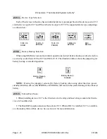
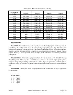
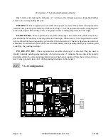
ance, line length, etc. A good trial value is 100 ohms in all three re sis tor lo ca tions. The fol low ing il lus -
tra tions show the cor rect jump er ing, driver IC in stal la tion, I/O con nec tor pin out, and ter mi na tion
re sis tor lo ca tions for each of the chan nels when used in RS- 485 mode.
991206
OPERATIONS MANUAL LBC-Plus
Page 2 - 9
WinSystems - "The Embedded Systems Authority"
1 2 3
o o o
1 2 3
o o o
U5 - Not In stalled
U6 - In stalled
U9 - In stalled
1 o o 6
2 o o 7
3 o o 8
4 o o 9
5 o
J9
J11
COM2 DB9
N/C
TX+
TX-
N/C
GND
RX+
RX-
N/C
N/C
VCC
R7
R6
R3
RX+
RX-
RS- 422 NOTE : When used in RS- 422 mode,
the trans mit ter must be en abled by set ting the RTS
bit in the Mo dem Con trol Reg is ter (Bit1).


