PPM-C412/Configuration
v1.0
www.winsystems.com
Page 25
7.12.2 J3 Power and Reset
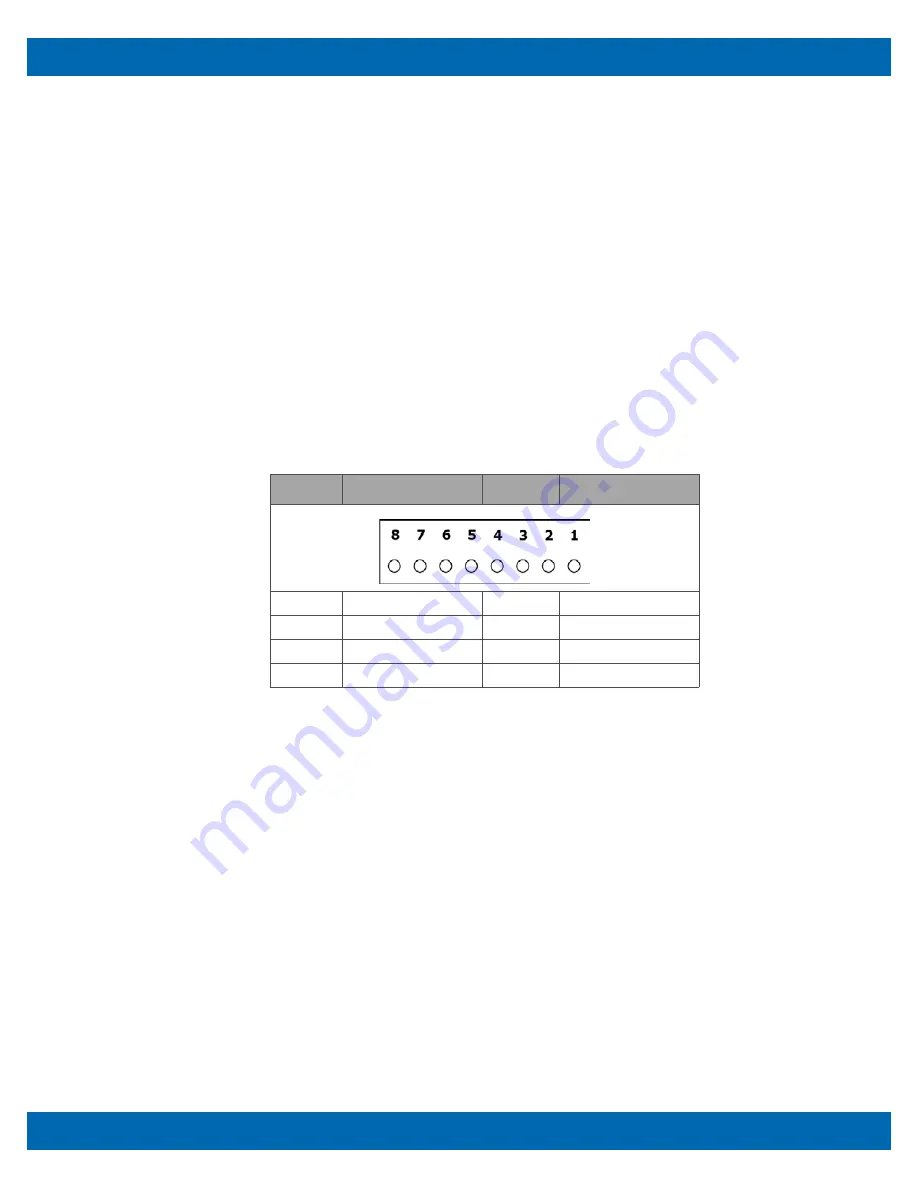
Power is applied to the PPM-C412 through the 8-pin Molex connector at
J3
. The
definitions for
J3
are listed in the table below.
An optional reset button can be connected between pin 8 and ground. Momentary
contact between pin 8 and ground causes the PPM-C412 to reset. There is also a reset
push-button supplied on the CBL-251-G-1-1.5 Multi-I/O cable. This cable is includes in
the cable set CBL-SET-412-1.
Power Fail Reset
A precision voltage comparator monitors the +5V status. Upon detection of an
out-of-tolerance condition, the board is reset. This action is critically important in the
event of brown-out or power fail conditions. The reset circuit also ensures that the
power is nominal before releasing reset. A reset condition occurs when V
CC
drops
between 4.6V and 4.75V for more than 150 ms.
Layout and Pin Reference
Connectors
•
PCB connector: Molex 22-12-2084 (PWR)
•
Mating connector: Molex 10-11-2083 (housing)
•
Mating connector: Molex 08-55-0124 (crimp)
7.12.3 J4 External Battery Connector
An optional external battery, connected to
J4
, supplies the PPM-C412 board with
standby power for the real-time clock and CMOS setup RAM. Extended temperature
lithium batteries are available from WinSystems, part numbers:
•
BAT-LTC-E-36-16-1
•
BAT-LTC-E-36-27-1
A power supervisory circuit contains the voltage sensing circuit and an internal power
switch to route the battery or standby voltage to the circuits selected for backup. The
Pin
Name
Pin
Name
1
-12V
5
GND
2
+12V
6
GND
3
+5V
7
GND
4
+5V
8
RESET


