PPM-C412/Configuration
v1.0
www.winsystems.com
Page 39
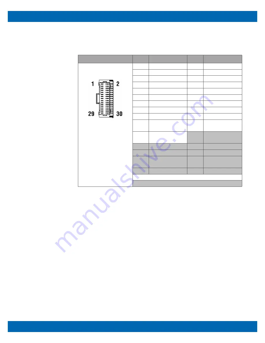
Use the audio portion to connect to the audio interface (pins 22 through 30, shaded in
the following table).
Layout and Pin Reference
Additional Information
The LVDS interface terminates at a portion of
J104
shared with the audio interface.
Connectors
•
PCB connector: Molex 501571-3007, 2x15, 1mm pitch Pico-Clasp right angle lock-
ing header
•
Mating connector: Molex 501189-3010 (housing)
•
Mating connector: Molex 501193-3000 (crimp)
•
WinSystems cables simplify connections to the board:
– CBL-LVDSAB-005-12: LVDS, audio, and backlight to 7” Ampire
– CBL-LVDSB-006-12: LVDS and backlight to 7” Ampire
– CBL-LVDSA-007-12: LVDS and audio to 12” Mitsubishi
– CBL-LVDSA-008-18: LVDS and audio to 12” Mitsubishi
– CBL-LVDSAB-003-08: LVDS, audio, and backlight to 6.5” AUO
– CBL-LVDSAB-009-18: LVDS, audio, and backlight to 12.1” AUO
Pin
Name
Pin
Name
1
LVDS_VCC (LVDS) 2
GND (LVDS)
3
D0- (LVDS)
4
D0+ (LVDS)
5
D1- (LVDS)
6
D1+ (LVDS)
7
LVDS_VCC (LVDS) 8
GND (LVDS)
9
D2- (LVDS)
10
D2+ (LVDS)
11
D3- (LVDS)
12
D3+ (LVDS)
13
LVDS_VCC (LVDS) 14
GND (LVDS)
15
CLK- (LVDS)
16
CLK+ (LVDS)
17
DDC_CLK (LVDS) 18
GND (LVDS)
19
DDC_DATA
(LVDS)
20
GND (LVDS)
21
GND (LVDS)
22
ANALOG_GND
(AUDIO)
23
OUT_R (AUDIO)
24
MIC_R (AUDIO)
25
OUT_L (AUDIO)
26
MIC_L (AUDIO)
27
ANALOG_GND
(AUDIO)
28
ANALOG_GND
(AUDIO)
29
LINE_R (AUDIO)
30
LINE_L (AUDIO)
Non-shaded cells designate LVDS interface.
Shaded cells designate audio interface.


