background image


13


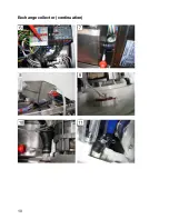
Procedures (continuation) 


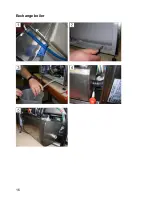
  Unplug the circulating pump 


Pull off the waste water hose that is connected to the upper 
distributor 

  Loosen clamp at the collector; do not remove it 

  Unscrew the collector and take it out 

  Disconnect the circulating pump of the collector 

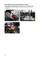
  Attach a new o-ring seal 


Installation of the new collector 

The installation is carried out in reverse order. At the same time a new 
pump wheel is to be installed. The pump wheel has a left-handed 
thread. 
 

After the assembly: 


Carry out a function test 


Ventilate the dosing devices 


Carry out a safety test according to VDE 0701 


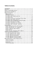
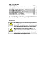
Summary of Contents for UC-L

Page 1: ...Winterhalter Undercounter Dishwashers UC Series Repair manual ...

Page 2: ...ange integrated water softener 26 Exchange heat exchanger radial fan 30 Flow schema 34 Model Standard not for UK Australia 34 Model Standard for UK Australia 35 Model integrated water softener 36 Model Energy 37 Model Energy integrated water softener 38 Options of the water treatment 39 UC with integrated water softener 39 UC with upstream water softener 39 UC with upstream desalination 40 UC with...

Page 3: ...g is carried out at the first start up and can be changed anytime Alternatively the machines are already programmed at the factory but can be re programmed on site Main dimensions of the 4 machines UC S UC M UC L UC XL Height 1 715 715 810 810 Width 460 600 600 600 Depth 602 5 602 5 602 5 641 5 Passage height 308 5 308 5 403 5 403 5 Rack size 2 400x400 500x500 500x500 500x500 500x540 Dimensions in...

Page 4: ... Energy UC M Energy UC L Energy UC XL Energy The vertical dimensions can be adapted with adjustable feet by 35 mm Through integrated containers for detergent and rinse aid the depth of all machines increases by 20 mm UC S UC M UC L UC XL ...

Page 5: ...nection cable page 4 3 Connection to the supply and return system on site water wastewater current according to the operating instructions 4 Adjust parameter P555 locking device page 4 Switching the boiler heating element The performance of the boiler heating element is determined by the switching of bridges The switching of the bridges must match the electrical supply and the fusing The bridges a...

Page 6: ...ment UC S Tighten the screwed cable connection at the backside of the machine Adjust parameter P555 See the connection scheme on the back of the stiffener wall to the electric installation compartment which value must be set for parameter P555 Setting range 0 1 2 or 3 Setting 0 no locking Setting 1 Boiler heating element locks against tank heating element Setting 2 Circulating pump or boiler heati...

Page 7: ...ameter set P 000 x Basic parameter set P 000 Mains network dishes rinse process UC M L XL UC S Dishes Standard 0001 0030 Standard 0006 0035 ReTemp 0007 0036 Glass Cool 0008 0037 dishes and glass Bistro Standard 0011 0040 3N 3 N 3 Cutlery Standard 0013 0042 Dishes Standard 0015 0044 Standard 0020 0049 ReTemp 0021 0050 Glass Cool 0022 0051 1N dishes and glass Bistro Standard 0025 0054 ...

Page 8: ...6 Save addresses for service and chemicals Enter date of day time and date of first start up Summary of the changed parameters Switch on the machine ...

Page 9: ...page 26 Exchange heat exchanger radial fan page 30 The repair instructions are described for machines with integrated chemical containers for detergent and rinse aid Safety notes Danger DANGER Danger of life due to components that are energised Disconnect the machine during all electrical work from the mains and check if it is free of voltage Warning When handling chemicals observe the safety note...

Page 10: ...8 Exchange collector ...

Page 11: ...e suction pipes into a measuring cup with water Successively activate the dosing devices in the actor programme in order to rinse them with water Drain the tank Switch the machine free of voltage Open the machine door Remove lower rotating wash field strainer and filter bottom Dry tank with a sponge cloth De install the machine Remove the right side panel Remove the right stiffener wall Pull off t...

Page 12: ...10 Exchange collector continuation ...

Page 13: ...on the boiler Put the machine onto the left side Remove the base cover Pull off the two black hoses on the air chamber air trap of the boiler Put the boiler onto the machine Unplug the diffusion sensor Move the wire hose clip that is located at the hose of the lower distributor upwards On the collector pull off the hose that leads to the Mediamat ...

Page 14: ...12 Exchange collector continuation ...

Page 15: ...lector and take it out Disconnect the circulating pump of the collector Attach a new o ring seal Installation of the new collector The installation is carried out in reverse order At the same time a new pump wheel is to be installed The pump wheel has a left handed thread After the assembly Carry out a function test Ventilate the dosing devices Carry out a safety test according to VDE 0701 ...

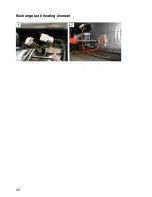
Page 16: ...14 Exchange boiler heating element ...

Page 17: ... Remove the right stiffener wall Completely drain boiler Disconnect the main power cable of the boiler heating element Unscrew 3 hexagonal nuts Pull out the boiler heating element If necessary clean boiler on the inside Replace the existing o ring seal by a new one Install the new boiler heating element Connect the main power cable Wires 1 3 connected to the gate at 2 4 6 Wires 4 6 connected to th...

Page 18: ...16 Exchange boiler ...

Page 19: ...chemical containers Remove the right stiffener wall Completely drain boiler Remove the hose at the back of the boiler Pull off the thermo sensor that is located on the boiler Unscrew the boiler Remove the hoses at the top and front of the boiler Unscrew the heating element Do not disconnect the heating element Pull out the old boiler and install the new one Use a new o ring seal Again tighten the ...

Page 20: ...18 Exchange the pressure transmitter of the boiler The following manual applies for the UC M L XL In models of the UC S Series the boiler is located behind the rear panel and is well accessible ...

Page 21: ...over plate Pull off the transparent hose at the air chamber air trap De install the pressure transmitter of the boiler green sticker with hose Install new pressure transmitter with new hose Mark the new pressure transmitter with a waterproof pen so that it is different from the pressure transmitter of the tank Install the cover plate Plug the bus cable into the Master Plug the grounding cable Inst...

Page 22: ...20 Exchange tank heating element ...

Page 23: ...special tool required Observe the safety notes on page 7 Drain the tank Remove the rear panel Unplug the cable of the tank heating element De install the tank heating element Install tank heating element with new o ring seal Plug the cable of the tank heating element Install the rear panel Carry out a function test Carry out a safety test according to VDE 0701 ...

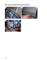
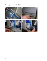
Page 24: ...22 Exchange pump head dosing device Fluidos ...

Page 25: ...suction pipes out of the chemical containers Put the suction pipes into a measuring cup with water Activate the dosing device in the actor programme in order to rinse it with water Remove the right stiffener wall Pull off suction and pressure hose at the dosing device Unscrew 4 screws Torx T15 Rotate the pump head anti clockwise by 90 and take it off Install new pump head Fix the suction and press...

Page 26: ...24 Exchange dosing device Fluidos ...

Page 27: ...a measuring cup with water Activate the dosing device in the actor programme in order to rinse it with water Remove the right stiffener wall Pull off suction and pressure hose at the dosing device Remove the left stiffener wall Unscrew the dosing device Fix new dosing device at the stiffener wall Fluidos DT Adjust the setting screw to MAX Fluidos DB Adjust the setting screw to MIN Fix the suction ...

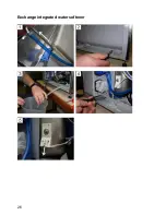
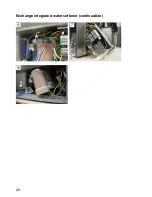
Page 28: ...26 Exchange integrated water softener ...

Page 29: ...hemical containers Put the suction pipes into a measuring cup with water Successively activate the dosing devices in the actor programme in order to rinse them with water Drain the tank Switch the machine free of voltage De install the machine Remove the right side panel Remove the right stiffener wall Completely drain boiler Remove the left stiffener wall together with the dosing devices Pull off...

Page 30: ...28 Exchange integrated water softener continuation ...

Page 31: ...e lower rotating wash field Unscrew the fastening nut of the water softener Pull off all cables and hoses at the water softener Take the water softener out of the machine Installation of the new water softener The installation is carried out in reverse order At the same time use a new o ring seal After the assembly Carry out a function test Ventilate the dosing devices Carry out a safety test acco...

Page 32: ...30 Exchange heat exchanger radial fan ...

Page 33: ...l the machine Pull forward the upper cover plate Pull off the bus cable that is attached to the Master Pull off the grounding cable remove the cover plate Pull off the hoses on the right of the heat exchanger On the riser pull off the hose attached to the heat exchanger Pull off the plug on the motor Unscrew the fastening of the motor Unscrew the fastening nut of the heat exchanger Lift the heat e...

Page 34: ...32 Exchange heat exchanger radial fan continuation ...

Page 35: ...no 30 000 189 Disconnect heat exchanger and radial fan of each other Remove the intake socket on the radial fan Fix the intake socket with new o ring seal on the new radial fan Fix the heat exchanger with new seal on the radial fan Installation of the complete unit Apply a new o ring seal The installation is carried out in reverse order The hose picture 7 must be fixed with 2 cable ties to the int...

Page 36: ...34 Flow schema Model Standard not for UK Australia 2 3 4 5 1 1 Solenoid valve 4 l min cold or warm water 2 Backflow protection type BPD 3 Boiler 4 Rinsing pump 5 Rinse aid dosing ...

Page 37: ...35 Model Standard for UK Australia 2 3 4 5 1 1 Solenoid valve 4 l min cold or warm water 2 Backflow protection type Airgap 3 Boiler 4 Rinsing pump 5 Rinse aid dosing ...

Page 38: ...36 Model integrated water softener 2 3 4 5 6 7 1 1 Solenoid valve 4 l min cold or warm water 2 Backflow protection type Airgap 3 Water softener 4 Boiler 5 Rinsing pump 6 Rinse aid dosing 7 Waste water ...

Page 39: ...37 Model Energy 3 2 4 5 6 1 1 Solenoid valve 3 l min cold water 2 Backflow protection type Airgap 3 Heat exchanger 4 Boiler 5 Rinsing pump 6 Rinse aid dosing ...

Page 40: ... Energy integrated water softener 4 2 3 5 6 7 8 1 1 Solenoid valve 3 l min cold water 2 Backflow protection type Airgap 3 Water softener 4 Heat exchanger 5 Boiler 6 Rinsing pump 7 Rinse aid dosing 8 Waste water ...

Page 41: ...livery of the UC 3 Dishwashing machine UC Series UC with upstream water softener MonoMatik DuoMatik 1 2 3 M D UC 4 with MonoMatik Water supply max 50 C Total hardness max 40 dH Copper concentr max 2 mg l with DuoMatik Water supply max 60 C Total hardness max 40 dH Copper concentr max 2 mg l Set parameter P503 0 1 Water shut off valve 2 Dirt trap included in delivery of the UC 3 MonoMatik or DuoMat...

Page 42: ...tial desalination VE 15 VE 20 complete desalination 4 Dishwashing machine UC Series UC with upstream reverse osmosis RoMatik 150 1 2 R150 UC 7 5 6 M D A 3 Fe 4 1 Water shut off valve 2 Dirt trap included in delivery of the UC 3 Desalination filter optional 4 Activated carbon filter optional 5 Water softener MonoMatik Duomatik optional 6 RoMatik 150 reverse osmosis 7 Dishwashing machine UC Series ...

Page 43: ... D A 3 Fe 4 1 Water shut off valve 2 Dirt trap included in delivery of the UC 3 Desalination filter optional 4 Activated carbon filter optional 5 Water softener MonoMatik Duomatik optional 6 RoMatik 160 RoMatik 210 RoMatik 420 reverse osmosis 7 Dishwashing machine UC Series ...

Page 44: ...or chemicals Possible causes for a bad cleaning result are 1 The detergent does not match the purpose 2 The rinse aid does not match the purpose 3 Dosing amount detergent rinse aid too low 4 Dosing device detergent rinse aid does not work electrically mechanically 5 Dosing hose bended not ventilated torn crystallised detergent 6 Storage container detergent rinse aid empty or interchanged 7 Deterge...

Page 45: ...manual washing up liquid Factor time Possible causes for a bad cleaning result are 1 Wrong programme selected 2 Wrongly set parameters Factor temperature Possible causes for a bad cleaning result are 1 Defective heating element in the tank or boiler 2 Wrongly set parameters 3 Defective temperature sensor on the tank or boiler Additionally the water quality plays an essential role when a perfect cl...

Page 46: ...44 ...

Page 47: ......

Page 48: ...Commercial Dishwashing Systems Tettnanger Strasse 72 88074 Meckenbeuren Germany Telephone 49 0 75 42 4 02 0 Telefax 49 0 75 42 4 02 1 87 www winterhalter biz info winterhalter biz Subject to technical alterations 89012679 00 04 09 ...

Reviews: