


PROCEDURE
1
Refer to
11.2 List of usual values and safeguard settings - general
for the usual values for
operation.
2
Prepare the control system for operation.
2.1
Set to ON the engine control system (ECS) and the remote control system (RCS).
2.2
Set to ON all circuit breakers in the power supply box E85.
2.3
Set to ON the control box for the cylinder oil filter (refer to the documentation of
the manufacturer).
3
Prepare the cooling water system for operation.
3.1
For an engine with a bypass cooling water system (refer to
), and when
the liner wall temperature is between 60°C and 90°C (eg when the engine is pre-
heated or after engine full stop for a sufficient period), release the unwanted air
with a high flow rate as follows:
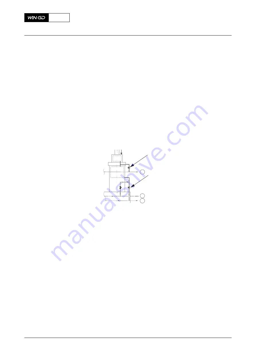
Fig 8-1
Cooling water system with bypass cooling
001
02
05
01
002
Legend
001
Shut-off valve
02
Connection 02 (cylinder liner cooling water
inlet)
002
Shut-off valve
05
Connection 05 (cylinder cooling water drain
outlet)
01
Connection 01 (cylinder cooling water inlet)
3.1.1
Close all shut-off valves (001) in the cylinder cover supply pipes (engine
connection 01).
NOTE:
This increases the pressure and thus the flow rate at the engine
connection 02.
3.1.2
Let the cooling water flow through the cylinder liners for approximately ten
minutes.
3.1.3
Close the shut-off valves (002) in the cylinder liner supply pipes of the first
half of cylinders (eg cylinder 1 to 3 for a 5 or 6 cylinder engine).
NOTE:
This increases again the pressure and thus the flow rate to the
other cylinders.
3.1.4
Let the cooling water flow through the other cylinder liners for
approximately ten minutes.
3.1.5
Open the shut-off valves (002) in the cylinder liner supply pipes of the first
half of cylinders.
X52
AA00-0000-00AAA-121A-A
Operation Manual
Prepare the engine before start
Winterthur Gas & Diesel Ltd.
- 281 -
Issue 002 2018-11


