2
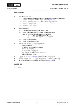
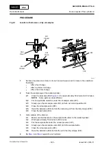
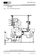
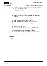
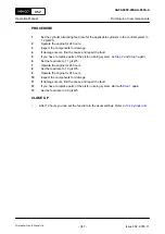
Make sure that compressed air is available at the shut-off valve (001,
) and fresh
water is available at the shut-off valve (009).
NOTE:
The schematic diagram in
is an example and is used for reference.
Some parts can look different.
3
) through the funnel (008) with fresh water and the specified
quantity of cleaning fluid (max. 30 liters).
3.1
Open the vent valve (002) and the valve (007) of the tank (006).
3.2
Carefully open the shut-off valve (009) in the water supply pipe and fill the
tank (006).
NOTE:
You can also use a hand-held container filled with cleaning fluid mixed
with fresh water to put into the funnel. When you use this method, make
sure that the shut-off valve in the supply pipe stays closed.
3.3
Close the shut-off valve (009) in the water supply pipe.
3.4
Close the vent valve (002) and the valve (007) of the tank (006).
4
Open the shut-off valve (001) in the compressed air supply pipe to pressurize the
tank (006).
5
Clean the scavenge air cooler (005) as follows:
5.1
Open the shut-off valve (003).
5.2
After no more cleaning water comes out, close the shut-off valve (003).
6
Close the shut-off valve (001) in the compressed air supply pipe.
7
Open the vent valve (002) to release the pressure in the tank (006).
8
After 10 minutes, do
again with fresh water (no cleaning fluid).
9
Do a check of the water separator for dirt.
10
If the water separator is dirty, clean the water separator (refer to the Maintenance Manual).
CLOSE UP
•
None
X52
AA00-6600-00AAA-200A-A
Operation Manual
Clean the scavenge air cooler during operation
Winterthur Gas & Diesel Ltd.
- 340 -
Issue 002 2018-11


