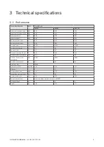
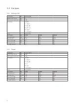


11
INSTALLATION MANUAL
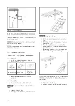
AIR HEATER TYPE DXC
1 2 3 4 5 6 7 8
ON
1
0
1 2 3 4 5 6 7 8
ON
1
0
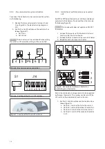
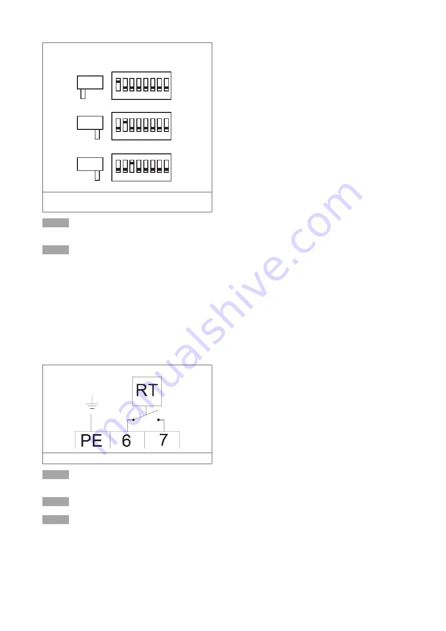
S1
J14
1 2 3 4 5 6 7 8
ON
1
0
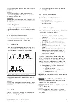
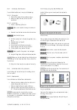
Figure 9 - Positions of the S1 and J14 switches for the
first three air heaters in a system
NOTICE
If the J14 switch of more than one air heater is
set to the same number, the system will not work.
NOTICE
The air heater must be switched off when setting
the switches. Otherwise the settings will have no effect.
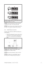
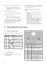
4.5.4
ON/OFF thermostat installation
To connect the air heater to an ON/OFF room thermostat,
do the following:
• Connect the two thermostat wires to terminal 6 and
7 (see figure 10 or the electrical wiring diagram in
§11). This is a 24 V connection for the thermostat
signal.
Figure 10 - ON/OFF thermostat connection
NOTICE
Never combine these connections with the
terminals 6 and 7 of other air heaters.
NOTICE
Always use separate relays for each air heater.
NOTICE
Do not connect an external power source to
these terminals. These terminals need a dry contact.