


20
9 Troubleshooting
If the air heater malfunctions, first check if the problem is
caused by external circumstances (e.g. no supply power).
If the problem is not caused by external circumstances,
use the tables and instructions in this chapter to fix the air
heater.
NOTICE
Please remember the built in waiting times of
the air heater; the signals of the LED’s and the code on the
display. Do not react too soon.
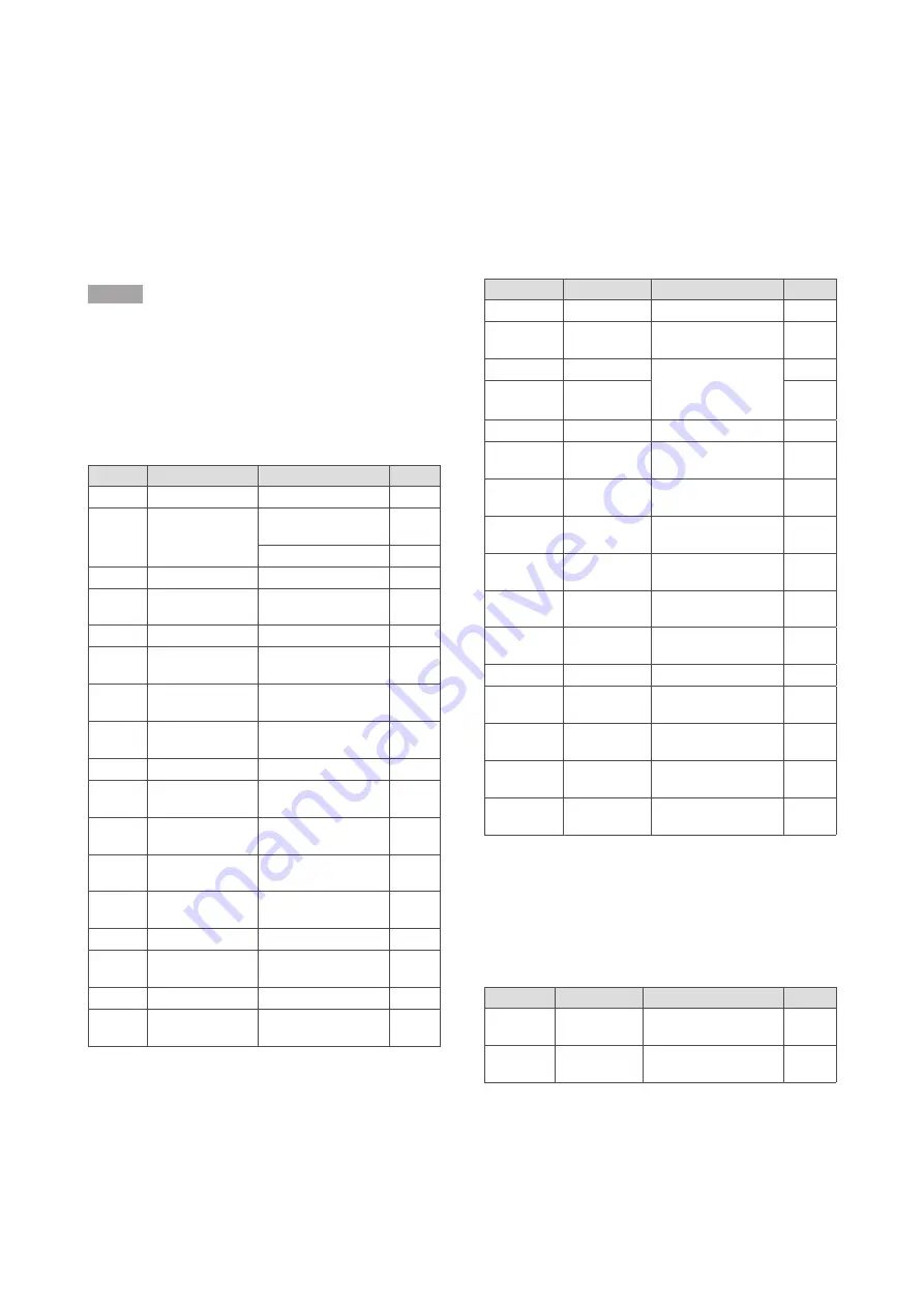
9.1 Volatile lock outs
The table below describes the volatile lock outs that can
occur. These can only be reset by hand.
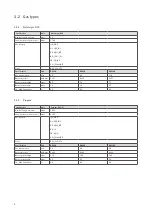
Display
Error type
Description
Case #
L-0
Internal error
Internal error
13
L-1
Ignition error
Flame lasts only 5 seconds
after ignition
1
No flame after ignition
2
L-2 and 3
Internal error
Internal error
13
L-4
E-error
E-error for more than 24
hours
12
L-8 to 12
Internal error
Internal error
13
L-13
Pressure switch error Pressure switch is closed
in stand-by mode
14
L-14
Pressure switch error Pressure switch does not
close during pre-purge
11
L-15
Overheating
Heat exchange sensor is
overheated
3
L-17 to 19 Internal error
Internal error
13
L-20
Flame error
Flame detected after
closing the gas valve
15
L-21
Flame error
Flame detected before
closing the gas valve
16
L-22
Flame error
Flame failure during
burning
5
L-25
Sensor error
Heat exchange sensor
failure
4
L-27 to 31 Internal error
Internal error
13
L-32
Sensor error
Heat exchange sensor
failure
4
L-33 to 38 Internal error
Internal error
13
L-43
Overheating
Heat exchange sensor is
overheated too often
3
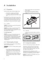
9.2 Temporary errors
The table below describes the temporary errors that can
occur. These will disappear automatically after the cause
has been resolved.
Display
Error type
Description
Case #
E-00 to 04
Internal error
Internal error
13
E-05
Overheating
Heat exchange sensor is
overheated
3
E-06 to 13
Internal error
Internal error
Flame detected when there
shouldn’t be one
13
E-14
Flame error
16
E-15 to 20
Internal error
Internal error
13
E-21 and 22
Heat exchanger
sensor error
Heat exchanger sensor not
detected
4
E-27 and 28
Heat exchanger
sensor error
Heat exchanger sensor
short-circuit
4
E-34
Reset button
error
Too many reset actions in a
short timespan
9
E-36
Overheating
Heat exchange sensor is
overheated
3
E-38 and 39
Heat exchanger
sensor error
Heat exchanger sensor not
detected
4
E-47 and 48
Heat exchanger
sensor error
Heat exchange sensor
short-circuit
4
E-49 to 64
Internal error
Internal error
13
E-65
Voltage too low
Supply voltage is too low
for over 1 minute
E-66
Voltage too high Supply voltage is too high
for over 1 minute
E-67
Pressure switch
error
Too many pressure switch
errors
11
E-69
Configuration
error
Heater configuration error 19
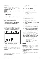
9.3 Warnings
The table below describes the temporary warnings that
can occur. The heater may still be working, or stops until
the cause has been resolved.
Display
Error type
Description
Case #
A-02
Configuration
error
Heater configuration error
19
A-07
Overheating
Heat exchange sensor is
almost overheated
3


