


24
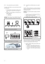
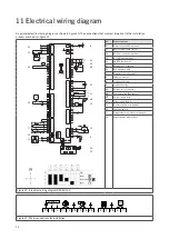
11 Electrical wiring diagram
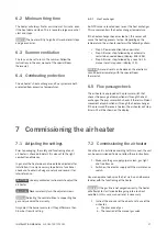
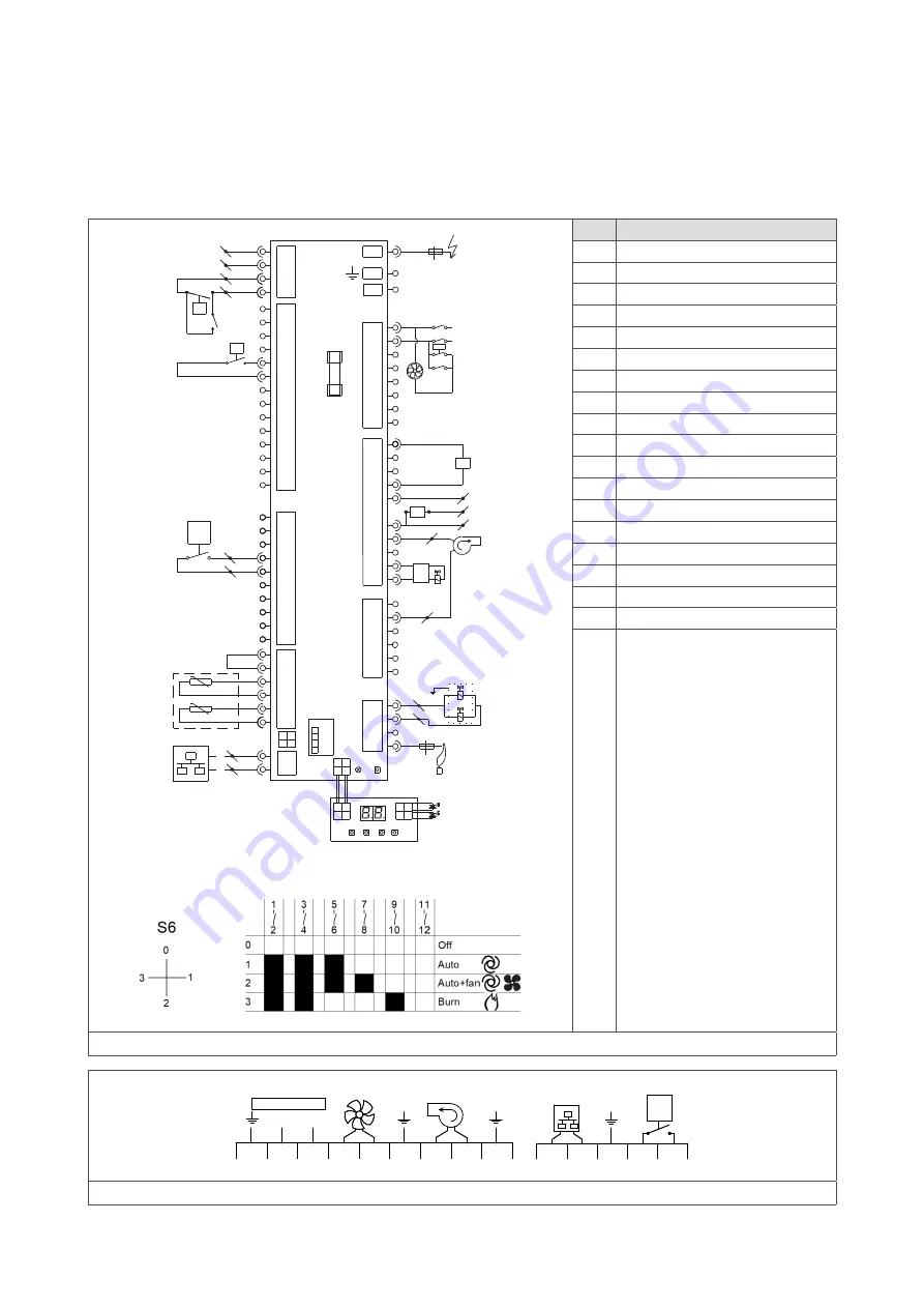
A complete electrical wiring diagram is shown in figure 20. The connections that are most important to the installation
process are shown in figure 21.
No.
Connection type
A1
Alarm output 230 V (optional)
C1
Bus communication system
C2
Modbus connection (optional)
C3
0 - 10 V input (optional)
C5
ON/OFF thermostat
D1
Display (2 x 7 segment)
D2
Red and green LED
F1
Glass fuse (5 x 20 mm 5AT)
I2
Ignition electrode
I3
Ionisation electrode
K1
System fan relay
K6
External reset (optional)
M4
Combustion fan (flue gases)
M5
System fan via relay
P4
Power supply (230 V)
S2
Pressure switch (combustion)
S6
Selection switch
T1
Temperature sensor (heat exchanger)
V2
High/low valve with rectifier
Figure 20 - Electrical wiring diagram DXC60-100
L
N
230 Vac
PE N
L
L
N
PE
11 12
13 14 PE
N
L
M1
4
5
6
7
PE
RT
Bus com
Figure 21 - Main connections for installation
20K@25°C
F1: 5AT
20K@25°C
J9- 1
J9- 3
J9- 2
J9- 4
J6- 1
J6- 8
J6- 2
J6- 9
J6- 3
J6- 10
J6- 4
J6- 11
J6- 5
J6- 12
J6- 6
J6- 13
J7- 1
J7- 2
J7- 3
J7- 4
J7- 5
J7- 6
J7- 7
J7- 8
J7- 9
J7- 10
J12- 1
J12- 4
J12- 2
J12- 5
J12- 3
J12- 6
J8- 1
J8- 2
J6- 7
J6- 14
T1
J2- 1..6
J1- 1
J1- 5
J1- 2
J1- 6
J1- 3
J1- 7
J1- 4
J1- 8
J3- 2
J3- 6
J3- 1
J3- 7
J3- 3
J3- 8
J3- 4
J3- 9
J3- 5
J3- 10
J4- 2
J4- 3
J4- 5
J4- 4
J4- 1
J4- 6
J5- 1
J5- 2
J5- 4
J5- 3
4 3
1
2
J25
LED RESET
4 3
1
2
4 3
1
2
J17
N
L
N
L ~
~
+
-
Rect.
K1
7
6
N
L
L on/off
K1
11
12
N
13
14
RT
4
3 1
2 J16
4
3
1
2
A/+
24V
B/-
GND
20 (GND)
21 (0-10V)
dP
C1
C2
C3
C5
D1
D2
I3
K1
M4
S2
T1
V2
I2
5
4
V2
M5
L
N
2
1
3
4
S6
8
7
10
9
S6
P4
K6
K6
11
13
Modbus
9 (A1)
10 (A2)
A1
8 (N)
K6
RT
A1
A2


