Instructions condensing Air heaters type XR version XR-GB-4001-a
Page 12/27
O
D
O
d
HOH
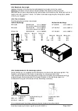
TR20-28 TR40-50 TR60-150
A 1280 1360 1850
B 500 550 955
d 80 100 130
D 125 150 200
HOH 110 140 225
A
B
TR20-28 TR40-50 TR60-150
d 80 100 130
D 125 150 200
HOH 110 140 225
600
ma
x
300
O
D
O
d
H
O
H
180
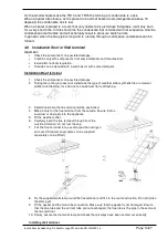
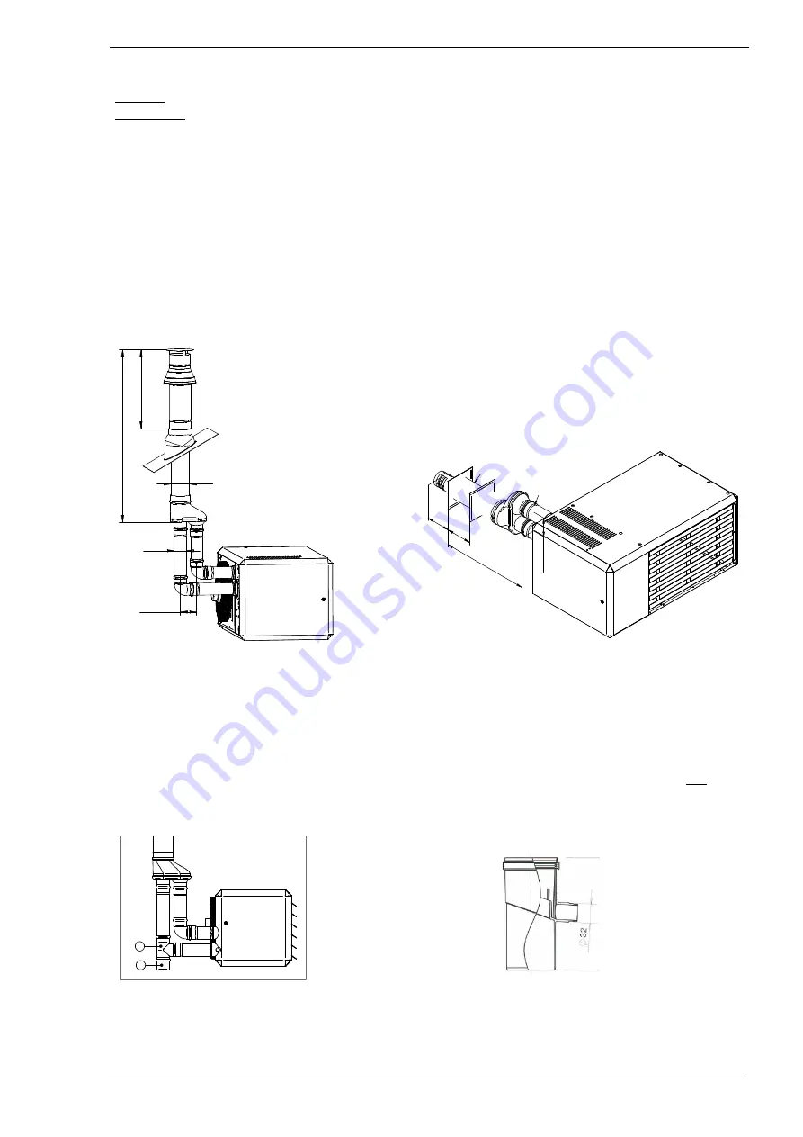
4.5.2 Maximum flue length
Vertical: 9 meters is the maximum length between the heater and its flue outlet.
Horizontal: 6 meters is the maximum length between the heater and the flue outlet.
When bends are used, the pressure drop will increase and therefore a 90° bend will count as 2
meters and a 45° bend as 1 meter. For further information regarding the flue system, please
contact your supplier.
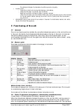
4.5.3 Flue terminals
The following flue terminals are allowed:
Vertical discharge
Horizontal discharge
TR10-28:
DDV 80/125
art.nr. IA8202
CT 80/125
art.nr. IA8113
For h>0,5m above roof IA8218
TR40-50:
DDV100/150
art.nr. IA8101
CT100/150
art.nr. IA8112
for h>0,5m above roof IA8107
TR60 -150
DDV130/200
art.nr. IA8305
CT130/200
art.nr. IA8312
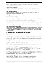
4.5.4 Condensation in the discharge system
During heating up, it is possible that condensation is formed in the discharge system. This
however, will evaporate if the heater is operating for a longer period of time.
If the straight length of the discharge flue is longer than 4 meters this condensation will not
evaporate again and accumulate in the heater! Isolation of the discharge pipes or a
condensation trap just at the heater is then absolutely necessary.
6
7
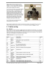
T-piece (6)
condensate trap (7)
condensate drain
Ø80 art.: IA8223
IA8225
IA8286
Ø100 art.: IA8176
IA8188
IA8288
This condensate will most likely not be formed on heaters more than 20kW.


