background image


Instructions condensing  Air heaters type XR version XR-GB-4001-a 


Page 4/27 

2.2.4 Protection from water, IP class 

The heater is not waterproof. This means that it may not be exposed to rain, spry or dripping 
water. The IP classification is IP00B 

2.2.5 Protection against dust 

The appliance is not designed for use in a very dusty environment. Dust may accumulate in the 
heater and may cause a defect of the heater. This is also the case for the room-thermostat 

2.2.6 Temperature 

Do not install the heater in places where the temperature can rise above 35°C. At higher 
temperatures the internal components will degrade much faster. This is not covered by the 
guaranty. 

2.2.7 Corrosive environment 

The heater should not be installed in areas containing any corrosive or explosive vapours. It 
should be prevented that chlorine or other corrosive containing vapours are sucked into the air 
intake. These vapours will result in corrosion of the heat exchanger and a leakage of 
condensate and flue gas. Defects caused by this are not covered by guaranty. Please consult 
your supplier. This is also the case for the room-thermostat 

2.2.8 Installation distances 

Keep sufficient distance between the heater and any obstruction, in connection with safety and 
access for service and maintenance. Pay particular attention to any flammable materials. 
Please take into account the possibility to open the door of the heater for the necessary service 
and maintenance work . Make sure the air flow to and from the heater is free from obstacles 
minimum 5 metres in front of the heater. Read the chapter “Installation” carefully. 
Also take the clearance distances from the flue system into account. 

2.2.9 Maintenance 

For the safe and proper operation of the heater periodical maintenance is necessary. When the 
heater is not serviced and cleaned in time, it could lead to damage to the heater or its 
surroundings. 

2.3  Guarantee 

The guarantee becomes void when the air heaters are not installed and serviced in accordance 
with this manual.


Summary of Contents for TR10

Page 1: ... TYPE TR Production from 2019 THIS DOCUMENT MUST ABSOLUTELY BE READ BEFORE STARTING THE INSTALLATION INSTRUCT USER AND LEAVE THIS DOCUMENT WITH HEATER FOR REFERENCE Date 01 02 2019 Instruction manual version TR GB 4001 a Heaters for GB ...

Page 2: ...IT 15 5 1 GENERAL 15 5 2 BURNER CYCLE 15 5 3 DELTA T REGULATION TEMPERATURE CONTROLLED DE STRATIFICATION FAN 15 5 4 SUMMER VENTILATION 16 5 5 HIGH LIMIT PROTECTION 16 5 6 FLUE TRANSPORT SUPERVISION 16 6 PUTTING INTO OPERATION AND ADJUSTMENT 16 6 1 GENERAL 16 6 2 START BY USING THE THERMOSTAT 16 6 3 START THROUGH THE DISPLAY IN THE HEATER 17 7 ADJUSTING THE GAS CONTROL 17 8 PROBLEM SOLVING 18 8 1 G...

Page 3: ...ain gas switch should be situated upstream in the gas line near the heater Turn off all electric power to the appliance After working on the heater always check for gas leaks Close the doors and hatches of the appliance 2 2 Important checks before installation 2 2 1 Pre check instructions Before unpacking and installation please check i e on the data badge if the heater is in accordance with the o...

Page 4: ... will result in corrosion of the heat exchanger and a leakage of condensate and flue gas Defects caused by this are not covered by guaranty Please consult your supplier This is also the case for the room thermostat 2 2 8 Installation distances Keep sufficient distance between the heater and any obstruction in connection with safety and access for service and maintenance Pay particular attention to...

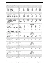
Page 5: ...150 150 Sound level dBA 42 42 42 45 45 48 50 Min suspension height horz throw M min 1 7 1 7 1 7 1 7 1 7 1 7 1 7 Min suspension height vertical throw M min 4 0 4 0 4 0 4 0 4 0 4 0 4 0 Maximum flue air length m 9 9 9 9 9 9 9 weight kg 50 50 55 67 70 85 100 Natural gas G20 I2H Nominal supply pressure G20 H mbar 20 Supply pressure min max G20 H mbar 17 25 Gas category II2H3P B P Class B23 C13 C33 Max ...

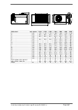
Page 6: ...50 250 250 250 250 250 250 I mm 190 190 190 190 190 225 225 K mm 110 110 110 110 110 140 140 M mm Ø80 Ø80 Ø80 Ø80 Ø80 Ø100 Ø100 N mm Ø80 Ø80 Ø80 Ø80 Ø80 Ø100 Ø100 O mm 1 2 1 2 1 2 1 2 1 2 3 4 3 4 P mm 250 250 250 470 470 470 600 R mm 235 235 235 145 145 195 195 S mm 80 80 80 95 95 95 95 T mm 175 175 175 75 75 165 165 U mm 50 50 50 80 80 70 80 For the purpose of suspension above below backside 4x M...

Page 7: ...Min suspension height horz throw M min 1 7 1 7 1 7 1 7 1 7 Min suspension height vertical throw M min 4 0 4 0 4 0 4 0 4 0 Maximum flue air length m 9 9 9 9 9 weight kg 135 150 200 230 260 Natural gas G20 I2H heater version 3 3 Nominal supply pressure G20 H mbar 20 Supply pressure min max G20 H mbar 17 25 Gas category II2H3P B P Class B23 C13 C33 Max gas consumption G20 H m3 h 6 9 8 6 11 2 14 0 16 ...

Page 8: ... 140 E mm 1335 1335 1335 1335 1335 F mm 1050 1050 1050 1050 1050 G mm 603 603 768 938 1103 H mm 580 580 580 580 580 I mm 123 123 123 123 123 K mm 225 225 225 225 225 M mm Ø130 Ø130 Ø130 Ø130 Ø130 N mm Ø130 Ø130 Ø130 Ø130 Ø130 O mm 3 4 3 4 3 4 3 4 3 4 P mm 570 570 740 910 1070 R mm 220 220 220 220 220 S mm 143 143 143 143 143 T mm 127 127 127 127 127 U mm 88 88 88 88 88 For the purpose of suspensio...

Page 9: ...ered Any obstacles should be a minimum of 5 metres away from the front of the heater When the heater is installed other than horizontal Always re adjust the CO2 setting from the gas valve The heaters are provided with M10 threaded sockets as fixing points see the dimension diagram Use preferably the Winterwarm suspension kits Make sure that after fitting there is no mechanical tension on any conne...

Page 10: ...y be converted by the manufacturer or its representative 4 4 Electrical connection 4 4 1 230Vac supply The installation must comply with local and national requirements as well as IEE regulations Never use a room thermostat to interrupt the electrical supply to the heater Make provisions to completely isolate the heater for maintenance purposes This can be an isolation switch min 3mm contact openi...

Page 11: ...able is not shielded and twisted the signal might become disturbed in an EMC unfriendly environment Keep the thermostat cable separated from mains cables Connect the earth shield of the cable only to the earth terminal in the heater If these guidelines are not followed it may result in malfunction of the installation or worse it could damage the thermostat or the electronics in the heater 4 4 4 Fu...

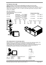
Page 12: ...ls are allowed Vertical discharge Horizontal discharge TR10 28 DDV 80 125 art nr IA8202 CT 80 125 art nr IA8113 For h 0 5m above roof IA8218 TR40 50 DDV100 150 art nr IA8101 CT100 150 art nr IA8112 for h 0 5m above roof IA8107 TR60 150 DDV130 200 art nr IA8305 CT130 200 art nr IA8312 4 5 4 Condensation in the discharge system During heating up it is possible that condensation is formed in the disc...

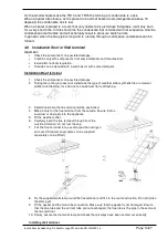
Page 13: ...stallation Roof terminal 1 Check the components on possible damages 2 Taking the roofing into account determine the type of weather collar synthetic file or universal pitched roof flashing for a flat roof an aluminium flat roof flashing 3 Determine where the flue terminal will be positioned 4 Make a hole for the flue terminal from the outside Ensure that no saw dust or dust gets into the appliance...

Page 14: ...go with the flue system Different manufacturers have different connections systems from the flue pipes It is not allowed to combine systems from different manufacturers The female sockets should have an depth of minimal 40 mm Install without mechanical force on the parts Inclination towards the appliance of 3 degrees 50 mm per meter to allow the condensate to flow to the heater Sealings If the flu...

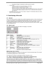
Page 15: ...d on the display in the heater Display Status Description 0 Stand by Standby waiting for heat demand 1 Reset Software reset 3 Pre check Zero position check pressure switch 4 Pre purge 30 seconds of pre ventilation from the combustion fan The pressure switch is checked 5 Pre ignition Ignition without opening the gas valve 6 Igniting Ignition 5 sec gas valve opens 7 Flame check Check if the flame is...

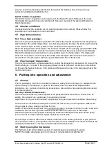
Page 16: ...here is sufficient movement of combustion air through the heat exchanger If the pressure difference is too low in the pre purge phase the fault L14 will occur 6 Putting into operation and adjustment 6 1 General Prior to packaging each unit is checked in detail on safety and functioning It is adjusted to the right efficiency of combustion In general the heater does not need to be adjusted after ins...

Page 17: ...ot necessary to adjust the gas control after putting the unit into operation In case it needs to be adjusted e g after fitting a new one this must be done only by a qualified person Only use calibrated instruments A poor adjustment can lead to overheating and or production of toxic carbon monoxide The burner pressures can be adjusted as follows Remove the cover from the gascontrol with the help of...

Page 18: ...ys be below 100 ppm 8 Problem solving 8 1 General When it turns out that the problem is not caused by the external circumstances i e no electric supply power or no gas please take the following instructions into account Please remember the built in waiting times of the heater do not react too soon and the signals of the LEDs and the code on the display on the electronic circuit board Volatile lock...

Page 19: ... sensor Sensor heat exchanger not detected 4 E 48 48 Heat exchanger sensor Heat exchanger sensor shortened 4 Case 1 Within 5 sec flame then flame failure The flame is not detected Check the ignition cable and electrode cable resistance 1k Ohm The electrical earth of the heater is poor The print board is defective Case 2 There is not enough gas pressure The mixture of gas air is poor adjust the gas...

Page 20: ...the gas valve The ionisation electrode is wet Dry or clean the electrode Or change the electrode Case 16 Flame detected before opening the gas valve Check it there is really a flame before ignition if that is the case replace the gas valve The ionisation electrode is wet Dry or clean the electrode Or change the electrode Heater does start but shows other problems Heater ignites explosively has oft...

Page 21: ...rush Clean the fan grid with a vacuum cleaner and a brush Put the burner back in renew the gasket After this check the heater on efficiency of combustion and adjust these if necessary Check the heater operates correctly 10 Examples electrical installation 10 1 Thermostat cable In all cases the communication between the heater and the thermostat is based on a two wire low voltage connection In the ...

Page 22: ... S1 on Each heater needs his own unique number to recognise the heater by the room thermostat The number of the heater can be set by the micro switch on the heater control in the heater The number at the upper position of the switch is the given number for that heater Make sure that each heater has its own unique number If more than one heater has the same number the system does not work The chang...

Page 23: ...J3 4 J3 9 J3 5 J3 10 J4 2 J4 3 J4 5 J4 4 J4 1 J4 6 J5 1 J5 2 J5 4 J5 3 4 3 1 2 J25 LED RESET 4 3 1 2 4 3 1 2 PE L on off 12 11 N L 5 4 J17 N L N L Rect 7 6 dP RT dT dT 11 Electrical diagram 11 1 Diagram with TR10 TR80 Ignition MAINS supply Neutral Line 230Vac Ground System Fan Flue fan Rectifier Gas valve High Low Gas Valve Ionisatiom Display LED s optional ON OFF thermostat optional Delta T senso...

Page 24: ...3 J3 8 J3 4 J3 9 J3 5 J3 10 J4 2 J4 3 J4 5 J4 4 J4 1 J4 6 J5 1 J5 2 J5 4 J5 3 4 3 1 2 J25 LED RESET 4 3 1 2 4 3 1 2 K1 1 PE N L 5 4 J17 N L N L Rect 7 6 dP L on off K1 11 12 RT dT dT 11 2 Diagram TR100 150 Ignition MAINS supply Neutral Line 230Vac Ground System Fan Flue fan Rectifier gas valve High Low Gas valve Ionisation Display LED s optional ON OFF thermostat optional Delta T sensor Pressure s...

Page 25: ...6712 GA6712 GA6712 GA 6712 GA 6712 GA6714 GA6714 15 Display pcb GY5902 GY5902 GY5902 GY5902 GY5902 GY5902 GY5902 24 External temp sensor IY3931 IY3931 IY3931 IY3931 IY3931 IY3931 IY3931 25 Rectifier block IY3921 IY3921 IY3921 IY3921 IY3921 IY3921 IY3921 No Description TR60 TR80 TR100 TR125 TR150 1 Burner IB3204 IB3204 IB3204 IB3204 IB3204 2 Ignition electrode GA3400 GA3400 GA3400 GA3400 GA3400 3 I...

Page 26: ...rs type XR version XR GB 4001 a Page 26 27 12 2 Exploded view TR10 TR20 12 3 Exploded view TR24 TR50 7 10 18 19 11 17 17 15 9 16 6 13 8 5 12 1 23 21 22 4 2 3 17 20 24 25 7 7 18 19 20 10 11 5 16 6 13 17 8 15 12 1 23 21 22 4 2 3 9 24 25 ...

Page 27: ...ers type XR version XR GB 4001 a Page 27 27 12 4 Exploded view TR60 TR100 12 5 Exploded view TR125 TR150 7 20 17 18 17 10 11 5 15 9 8 16 13 6 23 21 4 22 2 3 24 25 26 7 20 18 11 17 5 15 16 9 6 13 8 10 17 14 12 1 23 21 22 4 2 3 24 25 26 ...

Reviews: