background image


Instruction manual WWH-EC and WWH-LT Air heater    


Page 3/14 

2


Technical feature 

2.1  Table with data  

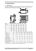
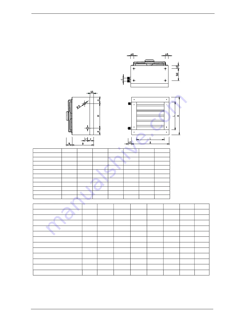
The WWH-EC is available in  8 models with capacities that differ  from 10 to 80 kW. The range of 10-80 
kW heaters is subdivided in 3 basic sizes. The type number of the appliance starts with the housing 
model (1,2 and 3). See table below for exact dimensions. 


Type 

115EC  120EC  235EC  245EC  350EC  365EC  380EC 

Model size 

505 

505 

679 

679 

834 

834 

834 

290 

290 

290 

290 

340 

340 

340 

40 

40 

43 

40 

40 

40 

43 

¾” 

¾” 

¾” 

1” 

1” 

1” 

1” 

81 

79.5 

81 

79.5 

81 

81 

79.5 

87.5 

75 

87 

74.5 

89.5 

89.5 

77 

87.5 

87.5 

87 

87 

89.5 

89.5 

89.5 

85 

85 

140 

140 

100 

46 

46 

375 

375 

535 

535 

690 

690 

690 

330 

343 

505 

518 

655 

655 

668 

(*) at water temperature of 90°/70° and environmental temperature of 15°C. 


Type  

Unit 

115EC 

120EC 

235EC 

245EC 

350EC  365EC  380EC 

Heating capacity (*) 

kW 

14.7 

19.7 

27.8 

42.4 

46.4 

54.4 

76.7 

Air output 

m

3

/h 

2200 

1950 

3900 

3500 

6150 

8500 

7600 

Throw horizontally 

16 

14 

22 

19 

21 

25 

21 

Throw vertical 

Electrical supply 

230 

230 

230 

230 

230 

230 

230 

Consumed current 

1.0 

1.1 

0.9 

1.1 

1.5 

1.8 

1.4 

Power consumption  

111 

123 

200 

250 

320 

400 

308 

Weight (incl. water) 

kg 

20 

21 

31 

32 

44 

61 

65 

Water connection (ext.)  

¾ 

¾ 

¾ 

Water sided pressure loss 

kPa 

Recommended susp. height  

m  

2.5 

2.5 

2.5 

2.5 

2.5 

2.5 

2.5 

Noise level (5m) 

dB(A) 

35-54 

35-54 

35-59 

35-57 

35-60 

35-56 

35-54 

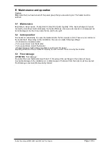
Summary of Contents for WWH-110LT

Page 1: ...ECHNICAL FEATURE 3 2 1 TABLE WITH DATA 3 2 2 USER S RESTRICTIONS 5 2 3 PRE CHECK 5 3 INSTALLATION 5 3 1 SUSPENSION 5 3 2 WATER CONNECTIONS 7 4 ELECTRICAL CONNECTION 8 4 1 230VAC SUPPLY 8 4 2 GENERAL FUNCTIONING OF THE UNIT 8 4 3 CONNECTING OPTIONS 8 4 4 CONTROL WITH ZONE VALVE 12 5 MAINTENANCE AND OPERATION 13 5 1 MAINTENANCE 13 5 2 SAFE OPERATION 13 5 3 FROST DAMAGE 13 6 WATER TEMPERATURES AIR VO...

Page 2: ...s on the heater will blow hot air The heater will give no heat when the fan is off no matter there is hot water running through the radiator or not The heater requires a control thermostat to arrange the supply of hot water and to switch the fan on off There are several options for control this will be described later in this manual For a better air distribution it s always better to choose 2 or m...

Page 3: ...7 5 87 87 89 5 89 5 89 5 H 85 85 140 140 100 46 46 L 375 375 535 535 690 690 690 M 330 343 505 518 655 655 668 at water temperature of 90 70 and environmental temperature of 15 C Type Unit 115EC 120EC 235EC 245EC 350EC 365EC 380EC Heating capacity kW 14 7 19 7 27 8 42 4 46 4 54 4 76 7 Air output m3 h 2200 1950 3900 3500 6150 8500 7600 Throw horizontally m 16 14 22 19 21 25 21 Throw vertical m 5 5 ...

Page 4: ...46 L 375 535 690 690 M 330 518 655 668 N 34 5 34 5 36 36 O 93 93 137 137 Type Unit 110LT 220LT 330LT 340LT Capacity 45 35 C kW 8 3 19 4 28 6 37 9 Cool capacity at 7 12 C kW 6 6 16 5 19 2 32 1 Cool capacity at 15 18 C kW 3 8 8 8 12 8 17 8 Cool capacity at 16 19 C kW 3 4 7 9 11 7 16 1 Air output m3 hr 1850 4150 5450 8850 Throw horizontally m 14 21 20 25 Throw vertical m 5 7 7 8 Electrical supply V 2...

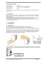
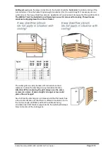
Page 5: ...er must make sure that the heater functions correctly and must instruct the user about safe operation of the heater 3 Installation 3 1 Suspension The WWH is provided with eight M10 suspension points on the side panels Use preferably the specially designed cantilever brackets or the ceiling mounting set Take care that the heater is placed stable and that there is no tension on the water sided conne...

Page 6: ...ir heater Types 115EC 120EC 110LT 235EC 245EC 220LT 350EC 365EC 380EC 330LT Model size 1 2 3 A 505 679 834 N 200 200 200 P 240 240 290 R 181 181 S 714 957 The outlet grill can easily be taken off turned around and replaced to direct the discharge in any desirable direction Attention When replacing the grill always use the same screws or screws of same length A longer screw could pierce the exchang...

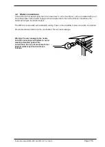
Page 7: ...n Do not twist these connections the heater will not give the desired output The WWH is not provided with a standard venting There is the possibility to place one when it is desired Prevent mechanical tension on the connections this will cause leakage Warning Prevent damage to the heater hold the connections with pliers to avoid twisting of welded parts of the connections Do not put excessive forc...

Page 8: ...the fan is turned on but the boiler water is cold there could be draught This must be prevented The installation should have some kind of control to make turning on off the hot water boiler and the fan of the WWH separately possible The WWH and the boiler are 2 separate systems Both systems need to be controlled There are several ways to do this It depends on the situation and needs of the user wh...

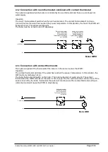
Page 9: ...me room as the WWH Operation The contact thermostat will close if the water has reached the pre set temperature In this situation the WWH will only discharge hot air The boiler thermostat will switch on the boiler The boiler will pump hot water around The contact thermostat of the WWH will close if the water is hot enough The fan will blow hot air into the room If the boiler is shut off by the boi...

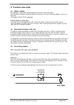
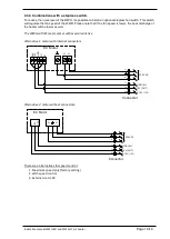
Page 10: ...ower the heat discharge of the heater will be lower as well The WWH with EC motor comes with several varieties Alternative 1 motor with internal connectors Alternative 2 motor without connectors There are 3 alternatives for speed control 1 Maximum speed only factory setting 2 With speed control 3 External via 0 10V L1 N T1 T2 S3 24V 10V GND D1 E1 L1 N 230V AC GND 0V 10V OUT 0 10V IN EC Motor Conne...

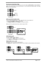
Page 11: ... pole connector Make sure that the potentiometer has a resistant value of 10kΩ 0 10V External control An external 0 10V current can be put on the connectors GND and E1 in the fan motor or on GND T1 and 0 10V IN S3 on the 6 pole connector Multiple WWH s on one control Eigh WWH s can be connected to 1 speed control The 10V T2 power supply may only be demanded from 1 WWH the others should not be conn...

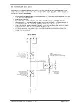
Page 12: ...powers the zone valve this will switch the boiler on Boiler makes hot water Contact thermostat measures water temperature If water temperature is higher than the temperature set CT will supply power to the WWH The fan will blow If a voltage regulator or external 0 10V signal has been applied this signal determines the fan speed If the requested temperature has been reached the RT will open the con...

Page 13: ...controlled by the room thermostat and or the fan speed control There are no controls on the heater itself Depending on the installation the user can make following settings Control main or isolation switch Turn up and down room thermostat Turn up and down contact thermostat Change fan speed with voltage regulator or externa 0 10V signal Adjusting direction of the air outlet is normally no user s a...

Page 14: ...0 54 0 45 0 37 0 27 0 22 0 18 6 2 WWH LT capacities at several water temperatures In situations where other inlet and return water temperatures are applied the registered heater capacity should be multiplied with the value in the table below The WWH LT is not classified for steam applications Air temperature Water temperature 0 C 5 C 10 C 15 C 18 C 20 C 45 35 C 1 76 1 51 1 25 1 00 0 81 0 74 50 30 ...

Reviews: