background image

16

Always place a bracket on or near a bend or elbow piece, 
except if the flue pipes before and after the elbow piece 
are shorter than 0,25 m. In this case, fix the second 
element after the elbow with a bracket.

Every flue discharge system needs to be secured with at 
least one bracket. The first bracket needs to be within the 
first 0,5 m of the air heater.

When installing a flue system inside a shaft, do the 
following:

1.  Check the components for possible damage or 

blockage.

2.  Check that the pipe is at the right slope (see 

Requirements).

3.  Mark the flue pipes and fresh air pipes to avoid 

mixing them up.

4.  Make sure that the pipes extend for at least 50 mm 

when passing through a wall or other obstacle.

5.  Fix the last element before entering the shaft in 

place. If the last element is an elbow piece, the 
next element must also be fixed in place.

6.  Check if ventilation openings and inspection 

hatches comply with national and local regulations.

6  Operating the air heater

6.1  Burner cycle

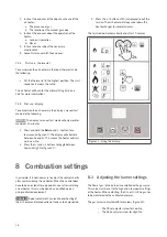
The air heater’s display shows the current status of the 
burner cycle (figure 20).

Figure 20 - Display of the air heater

Display

Status

Description

0

Stand-by

Waiting for heat demand.

1

Reset

Software reset.

3

Pre-check

Zero position check pressure switch.

4

Pre-purge

30 seconds of pre ventilation by the 
combustion fan. The pressure switch is 
checked.

5

Pre-ignition

Ignition without opening the gas valve.

6

Ignition

5 seconds of ignition. The gas valve opens.

7

Flame check The air heater checks if the flame is present.

8

Burn

The heater fires up and starts to modulate.

9

Minimum

Before the flame stops, the burner will 
modulate to minimum power.

10

Burner off

The gas valve closes. The flame stops.

11

Post purge

Burner fan purges with fresh air.

System fan cools the heat exchanger.

6.2  Minimum firing time

The heater will always fire for a minimum of 4 minutes, 
even if the heat demand stops. This is to avoid a large 
amount of start and stops and to prevent condensate from 
accumulating in the flue system.

 NOTICE 

 The heater will try to ignite 2 times before it stops 

and gives an error.

6.3  Delta-T-regulation

The air heater can function as a de-stratification fan. This 
is called delta-T regulation and it is done via the room 
thermostat, with a temperate measurement sensor that is 
located on the air heater.

The system fan is activated when the temperature-
difference between the sensor on the heater (the delta-T 
NTC sensor) and the sensor in the thermostat is bigger 
than 8

o

C (standard factory setting). This procedure 

ensures an even distribution of temperature throughout 
the building, thus acting as a fully automatic de-
stratification fan.

6.3.1 

Switch off delta-T-regulation

Delta-T regulation can be switched off when it is not 
desired (e.g. when it causes discomfort). This can be 
done in the 

Settings

 menu on the room thermostat. See 

the user manual of the special Room thermostat for more 
information.

 NOTICE 

 Delta-T regulation is automatically switched 

off when the delta-T sensor (sensor terminal J6) is 
disconnected.

Summary of Contents for XR

Page 1: ...XR en v2 0 12 2019 INSTALLATION MANUAL AIR HEATER TYPE XR ...

Page 2: ... flue terminal 14 6 Operating the air heater 16 6 1 Burner cycle 16 6 2 Minimum firing time 16 6 3 Delta T regulation 16 6 4 Summer ventilation 17 6 5 Overheating protection 17 6 6 Flue passage check 17 7 Commissioning the air heater 17 7 1 Adjusting the settings 17 7 2 Commissioning the air heater 17 8 Combustion settings 18 8 1 Adjusting the burner settings 18 8 2 Converting to another gas type ...

Page 3: ...ation and void the warranty 2 Safety instructions Always follow the safety instructions in this chapter when installing using or performing maintenance on this air heater 2 1 Installation CAUTION This air heater must be installed and maintained by an authorized qualified and competent installer using calibrated equipment NOTICE This air heater must be installed and maintained in accordance with th...

Page 4: ...ppliance in a safe way and understand the hazards involved WARNING Children shall not play with the air heater WARNING Children shall not clean and maintain this air heater without supervision 3 Technical specifications 3 1 Performance Technical specification Unit Type XR 4 1 ERP2018 XR10 XR20 XR30 XR40 XR50 XR60 Net nominal heat input max kW 14 0 22 8 32 0 44 0 55 0 66 0 Net nominal heat input mi...

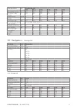
Page 5: ...6 37 38 78 80 82 3 2 Gas types 3 2 1 Natural gas G20 Specification Unit Natural gas G20 Nominal supply pressure mbar 20 Supply pressure min max mbar 17 25 Gas category I2H BE I2 E s FR I2 ESI NL I2 EK DE I2 ELL Class B23 C13 C33 Specification Unit XR10 XR20 XR30 XR40 XR50 XR60 Gas consumption max m3 h 1 5 2 4 3 4 4 7 5 8 7 0 CO2 High 9 0 9 0 9 0 9 1 9 1 9 0 CO2 Low 8 5 8 6 8 5 8 6 8 5 8 8 O2 High ...

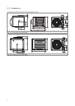
Page 6: ...s of this air heater can be found in figures 1 and 2 60 490 245 285 495 575 85 106 60 90 680 M10 110 Figure 1 Dimensions of the XR10 XR30 150 650 20 70 546 400 670 495 140 150 106 M10 M10 105 120 Figure 2 Dimensions of the XR40 XR60 ...

Page 7: ... IIE regulations that incorporate the gas safety regulations 4 2 Positioning the air heater Keep the following requirements in mind when choosing a location to install your air heater WARNING Never install an air heater close to flammable materials Keep sufficient distance between the heater and any obstructions This is both for safety reasons and to allow access for service and maintenance figure...

Page 8: ... 6 Vertical suspension kit Figure 7 Suspension adapter The air heater is equipped with threaded sockets to suspend the unit see 11 Use the suspension kit that is compatible with your air heater The suspension kit is not delivered with the air heater Contact your supplier ...

Page 9: ... The air heater requires an earthed power supply of 230 V AC A supply of 400 V AC Neutral is optional The control circuit is a two wire low voltage bus communication Figure 8 The air heater s connection clamps Connect the wires of the mains cable to the clamps in the connection box figure 8 Completely isolate the air heater for maintenance purposes Use an isolation switch min 3 mm contact opening ...

Page 10: ...ignal NOTICE A cable that is not shielded and twisted may result in a disturbed communication in an EMC unfriendly environment 4 5 2 Modulating room thermostat installation To connect the air heater to an MTS or MTC thermostat do the following 1 Connect the two control wires to terminals 4 and 5 see figure 9 or the electrical wiring diagram in 11 a Set the S1 and J14 switches on the control unit a...

Page 11: ...er to 2 etc 1 2 3 4 5 6 7 8 ON 1 0 1 2 3 4 5 6 7 8 ON 1 0 S1 J14 1 2 3 4 5 6 7 8 ON 1 0 Figure 13 Positions of the S1 and J14 switches for the first three air heaters in a system NOTICE If the J14 switch of more than one air heater is set to the same number the system will not work NOTICE The air heater must be switched off when setting the switches Otherwise the settings will have no effect 4 5 4...

Page 12: ...installation will be approved NOTICE Local regulations can require the flue terminal to be placed at least 0 6 m above roof level NOTICE Local regulations can require a minimum distance between the flue terminal and air ventilation openings on the building 5 1 Flue terminals The following flue terminals are compatible with this air heater Model s Vertical discharge Flue terminal Art Nr XR10 until ...

Page 13: ...p This condensate will evaporate if the heater is operating for a longer period of time The forming of condensate depends on the following factors 5 3 1 Air heater type Condensate is especially likely to form in the smaller heaters 25 kW Condensate will most likely not form in the larger heaters 25 kW 5 3 2 Air heater location When an air heater burns frequently and is placed in a normally heated ...

Page 14: ...is or dust gets into the air heater 2 Install the weather collar 3 Carefully insert the flue terminal from the outside CAUTION Do not rotate the cap 4 Put the flue terminal into a vertical position Use a level 5 OPTIONAL If desired fit cover plates These are supplied separately 6 Place the supplied wall clamp around the flue terminal and fit it to the roof construction Do not tighten the clamp yet...

Page 15: ... use different connection systems for flue pipes It is not allowed to combine systems from different manufacturers 5 4 3 2 Elements system ALU FIX thick wall An ALU FIX flue system is created with four elements figure 19 Figure 19 The elements of a flue system 5 4 3 3 Seals The connection between the different flue elements must be made airtight and waterproof with silicon seals CAUTION If the flu...

Page 16: ... seconds of ignition The gas valve opens 7 Flame check The air heater checks if the flame is present 8 Burn The heater fires up and starts to modulate 9 Minimum Before the flame stops the burner will modulate to minimum power 10 Burner off The gas valve closes The flame stops 11 Post purge Burner fan purges with fresh air System fan cools the heat exchanger 6 2 Minimum firing time The heater will ...

Page 17: ...c circuit board or remotely with the special Room thermostat 6 6 Flue passage check The air heater is equipped with a pressure switch that checks the passage of combustion air through the heat exchanger The pressure switch checks if there is sufficient movement of combustion air through the heat exchanger only during the pre purge phase If the pressure difference is too low the air heater will not...

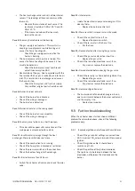
Page 18: ...start up in Low fire 2 Press the and buttons to toggle between Low and High fire figure 21 3 Press the button until 0 is displayed to exit the service The air heater will always cool down the heat exchanger for several minutes The test mode will automatically end after 10 minutes Figure 21 Using the display 8 Combustion settings In principle it is not necessary to adjust the control shortly after ...

Page 19: ...The concentration of CO should always be below 100 ppm 8 2 Converting to another gas type CAUTION The air heater s gas type may only be converted by the manufacturer or its representative Contact your supplier for more information 9 Troubleshooting If the air heater malfunctions first check if the problem is caused by external circumstances e g no supply power If the problem is not caused by exter...

Page 20: ...er 1 minute E 66 Voltage too high Supply voltage is too high for over 1 minute E 67 Pressure switch error Too many pressure switch errors 11 E 68 Flue temperature error Flue sensor is overheated 3 E 69 Configuration error Heater configuration error 19 9 3 Warnings The table below describes the temporary warnings that can occur The heater may still be working or stops until the cause has been resol...

Page 21: ...ck if the combustion fan is running Check if the flue system is blocked or restricted Check the pressure switch and the connections Check the heat exchanger for flue leakage Case 12 E error for more than 24 hours Switch the air heater off and on and check the error code Case 13 Internal error Isolate the electrical supply and reenergise If this does not help Replace the burner control unit Case 14...

Page 22: ...servicing 10 2 Basic maintenance To perform basic maintenance on the air heater do the following CAUTION When cleaning parts of the air heater use a dry cloth brush compressed air or a vacuum cleaner Never use a steel brush 1 Inspect the outside of the heat exchanger 2 Clean the fan guard on the outside of the heater Clean the fan blades if required 3 Open the access panel 4 Clean the inside of th...

Page 23: ... distance between the two electrodes should be mm figure 24 c Check the setting of the ignition electrode The spark should be formed between the two electrodes not between the electrode and the burner Figure 23 Distance between the electrode and the burner Figure 24 Distance between the two electrodes 7 Reassemble the burner unit and install it back in the air heater Use new gaskets ...

Page 24: ... triac 11 12 N L 5 4 J17 100K 25 C 7 6 J2 L N 5 4 3 2 1 4 3 1 2 J16 4 3 1 2 A 24V B GND 20 GND 21 0 10V dP C2 C3 C4 C6 D1 D2 E1 I1 M2 M3 P1 S2 T1 T2 T4 V1 PE K6 K6 11 13 Modbus 9 A1 10 A2 A1 8 N K6 A1 A2 RT No Connection type A1 Alarm output 230 V optional C2 Modbus connection optional C3 0 10 V input optional D1 Display 2 x 7 segment D2 Red and green LED E1 Power line EMI filter F1 Glass fuse 5 x...

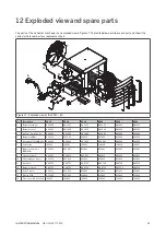
Page 25: ...3460 GA3460 GA3460 GA3460 GA3460 5 Burner fan EBM GY4523 GY4523 GY4523 GY4523 GY4523 GY4523 6 Gas valve SIT SIGMA 848 GA3000 GA3000 GA3000 GA3000 GA3000 GA3000 7 System fan IX4201 IX4201 IX4201 IH4206 IH4206 IX4207 8 Burner control unit EBM966 GY5901 GY5901 GY5901 GY5901 GY5901 GY5901 9 Pressure switch GX3932 GX3932 GX3932 GX3932 GX3932 GX3932 10 Heat exchange sensor GY3932 GY3932 GY3932 GY3932 GY...

Page 26: ...relating to appliances burning gaseous fuels 2014 35 EU LVD relating to the electric safety of appliances 2014 30 EU EMC relating to electromagnetic compatibility of appliances 2006 42 EG MD relating to the safety of machinery Goods should be installed and used in accordance with our instructions and with the applicable local and international rules Installation should be done by an authorized qua...

Page 27: ...27 INSTRUCTION MANUAL AIR HEATER TYPE XR ...

Page 28: ......

Reviews: