25
INSTRUCTION MANUAL
AIR HEATER TYPE XR
12 Exploded view and spare parts
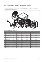
The parts of the air heater are shown in an exploded view in figure 27. The table below describes each part and shows the
correct article number for a replacement part.
11
5
6
13
8
1
2
9
12
11
14
10
7
Figure 27 - Exploded view of the XR10 - 60
No.
Description
XR10
XR20
XR30
XR40
XR50
XR60
1
Burner natural gas
GA3206
GA3207
GA3208
GA3208
GA3210
GA3212
1
Burner propane
GA3224
GA3226
GA3228
GA3228
GA3230
GA3232
2
Ignition / ionisation set
GA3460
GA3460
GA3460
GA3460
GA3460
GA3460
5
Burner fan EBM
GY4523
GY4523
GY4523
GY4523
GY4523
GY4523
6
Gas valve SIT SIGMA 848
GA3000
GA3000
GA3000
GA3000
GA3000
GA3000
7
System fan
IX4201
IX4201
IX4201
IH4206
IH4206
IX4207
8
Burner control unit
(EBM966)
GY5901
GY5901
GY5901
GY5901
GY5901
GY5901
9
Pressure switch
GX3932
GX3932
GX3932
GX3932
GX3932
GX3932
10
Heat exchange sensor
GY3932
GY3932
GY3932
GY3932
GY3932
GY3932
11
Gasket set
GA6702
GA6702
GA6702
GA6706
GA6706
GA6706
12
Burner isolation
GA6700
GA6700
GA6700
GA6704
GA6704
GA6704
13
Delta-T sensor
GY3931
GY3931
GY3931
GY3931
GY3931
GY3931
14
Display PCB
GY5902
GY5902
GY5902
GY5902
GY5902
GY5902
15
Flue sensor XR (optional)
IX3930
IX3930
IX3930
IX3930
IX3930
IX3930


