9
INSTRUCTION MANUAL
AIR HEATER TYPE XR
4.3 Gas type & connection
The unit is suited for the use of natural gas or propane gas.
The specific gas type that a heater is set up for can be
found on the packaging labels and on the heater badge.
The heater can be converted to another gas type. Contact
your supplier for more information.
The working and standing supply pressure must be
a minimum of 17 mbar, and a maximum of 50 mbar,
measured at the inlet pressure nipple of the gas control in
the heater.
NOTICE
The supply line’s manual isolation valve must be
placed within reach of the heater.
NOTICE
All gas supply lines must be mounted without any
mechanical tension.
NOTICE
Always clean the inside of a gas supply line
before connecting it to the air heater. Place a gas filter in
the supply line when needed.
CAUTION!
When using pressures above 60 mbar to test
the supply lines, always close the manual isolation valve of
the air heater.
For United Kingdom only:
The supply line for gas must comply with the Gas
Engineers publications UP-1 and UP-2, as well as with BS
6891.
4.4 Electrical connection
The electrical installation must comply with local and
national requirements as well as IEE regulations.
4.4.1
Power supply
The air heater requires an earthed power supply of 230 V/
AC. A supply of 400 V/AC + Neutral is optional. The control
circuit is a two wire low voltage bus communication.
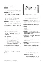
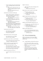
Figure 8 - The air heater's connection clamps
• Connect the wires of the mains cable to the clamps
in the connection box (figure 8).
• Completely isolate the air heater for maintenance
purposes. Use an isolation switch (min. 3 mm
contact opening gap), a power plug or a non-
switched fuse spur. See the electrical wiring
diagram in §11.
4.4.2 Fuse
One fuse is present on the air heater’s control board (see
the electrical wiring diagram in §11).
• When replacing this fuse, always use one of the
same type (5AT).
4.5 Room thermostat
The heater can only be controlled with one of the following
Winterwarm modulating room thermostats:
•
The MTS
: a modulating digital thermostat.
•
The MTC
: a modulating digital clock thermostat
with optimiser.
•
Interface module
; a specially designed interface
module for BMS systems. Contact your supplier for
more information.
•
ON/OFF thermostat:
a simple on/off thermostat.
WARNING!
Never use a room thermostat to interrupt the
electric power supply to the heater.
4.5.1 Installation requirements
Following these requirements when placing the thermostat
to ensure the heater functions correctly:
• Make sure that air can circulate around the
thermostat.
• Make sure the sun does not shine directly upon the
thermostat.
• Do not place the thermostat on a cold wall.

