1143100
SmartPAC PRO User Manual
138
Chapter 4 – SmartPAC PRO Program Mode
NOTICE
When you select TOGGLE or PULSE, the ProCamPAC channel associated with output from that
batch counter displays on the Counters, Figure 4-13, page 134. See
for information
about ProCamPAC outputs.
2.
If you select PULSE as the output mode in step 2, move the highlight bar to the PULSE TIME
(MSEC) column, and press ENTER. The Numeric Entry displays.
3.
Key in a value for the cam channel On time in milliseconds (maximum value, 9,999 mS, or about
10 seconds), then press ENTER. The value you keyed in displays in the PULSE TIME (MSEC)
column for the specified Batch counter.
4.
Move the highlight bar to the INCREMENT MODE column, then press ENTER to toggle
between the STROKE and GOOD PARTS options until the setting you want is displayed.
5.
Repeat steps 2 through 5 for other Batch counters, as necessary.
6.
Press Back to return to the Counters screen.
Setting Counter Increment Angle
The crankshaft angle at which counters are incremented is set at the factory to a default value of 270
.
This value is satisfactory for counting parts, but if you have programmed Batch counter outputs to
control automation, increment angles for those counters should be set to the angle at which you want
the automation to activate. The Counter Mode Selections screen allows you to set a common
increment angle for Strokes, Good Parts, and Batch 1 counters and separate increment angles for
Batch 2 and Batch 3 counters. To change default increment angles, do the following:
1.
On the Counter Mode Selections screen, move the highlight bar to the increment angle value for
the counter you want to adjust (e.g., Batch 2), then press ENTER. The Numeric Entry window
displays.
2.
Key in a new increment angle value, then press ENTER. The value you entered is displayed on
the Counter Mode Selections screen.
3.
Repeat steps 1 and 2 for other counters, as necessary.
Setting Parts per Stroke or Strokes per Part
SmartPAC PRO allows you to control how the Strokes and Good Parts counters increment in relation
to each other. You can specify the number of parts made during each stroke, in which case the Good
Parts counter will increment in multiple units (e.g., 2, 3, etc.) for each increment of the Strokes
counter. This setting is useful in multiple-up die applications.
Conversely, you can specify the number of strokes required to make each part, causing the Good
Parts counter to increment only once for multiple increments (e.g., 2, 3, etc.) of the Strokes counter.
This setting is useful in die applications with a gagged cutoff.
To set the number of parts made per stroke or number of strokes required to make a part, do the
following:
1.
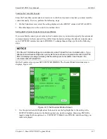
On the Counter Mode Selections screen, press the ADVANCED MODES button. The Advanced
Counter Mode Selections screen, Figure 4-16.
Summary of Contents for SmartPAC PRO
Page 1: ......
Page 2: ......
Page 4: ......
Page 6: ......
Page 20: ......
Page 22: ......
Page 24: ......
Page 42: ...1143100 SmartPAC PRO User Manual 42 Chapter 1 Introduction to SmartPAC PRO ...
Page 142: ...1143100 SmartPAC PRO User Manual 142 Chapter 4 SmartPAC PRO Program Mode ...
Page 200: ...1143100 SmartPAC PRO User Manual 200 Chapter 6 Using DiProPAC Die Protection Optional ...
Page 222: ...1143100 SmartPAC PRO User Manual 222 Chapter 7 ProCamPAC Instructions ...
Page 254: ...1143100 SmartPAC PRO User Manual Appendix C SmartView Remote Viewing and E mail Setup 254 ...
Page 280: ...SmartPAC PRO User Manual 1143100 280 Appendix C Reporting Downtime and Scrap to SFC ...
Page 290: ...SmartPAC PRO User Manual 1143100 290 Index Y yellow fault 232 yellow sensor 169 ...
Page 292: ......
Page 294: ......
Page 296: ......
Page 298: ......
Page 300: ......
Page 301: ......
Page 302: ......
Page 303: ......
Page 304: ......
Page 305: ......
Page 306: ......
Page 307: ......
Page 308: ......
Page 309: ......
Page 310: ......
Page 311: ......
Page 312: ......
Page 313: ......
Page 314: ......
Page 315: ......
Page 316: ......
Page 317: ......
Page 318: ......

