SmartPAC PRO User Manual
1143100
Chapter 2 – Installing SmartPAC PRO
53
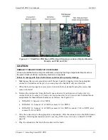
Figure 2-6. Location of Terminal Blocks TB1 through TB8
CAUTION
DAMAGE TO RESOLVER
Be sure that the sprocket or gear driving the resolver chain or timing belt is mounted so that it is
centered on the crankshaft. If the gear or sprocket is mounted off-center, the resulting loads on the
resolver shaft may cause the resolver to fail.
Failure to comply with these instructions could result in property damage.
Wintriss Controls Group stocks a spring-loaded base (part# 4194300) with a hole pattern that matches
the hole pattern on the resolver.
The resolver can turn in a clockwise or counterclockwise direction. You can change the direction of
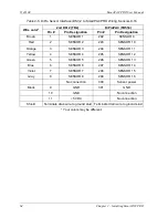
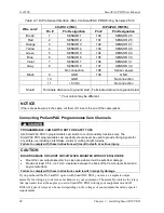
rotation by swapping the black and yellow wires on the resolver connector (see Table 2-2, page 55).
When designing the drive for the resolver, make sure that the drive allows for adjustment of the
resolver to its zero position at top dead center. All sprockets must be keyed or pinned. The resolver
shaft has a standard key.
Design a method of driving the resolver directly from the crankshaft, using a chain or timing belt (not
a V belt) and sprockets. Use either an idler sprocket or spring-loaded resolver base to compensate for
slack or stretch.
Observe these additional precautions when designing the resolver drive:
•
Do not use a long, sloppy chain. The distance between the center of the resolver shaft and the
center of the crankshaft should be no more than 3 feet (1 m).
•
Do not use gears, right-angle joints, or shafts with universal joints because these will develop too
much backlash or too much play.
Summary of Contents for SmartPAC PRO
Page 1: ......
Page 2: ......
Page 4: ......
Page 6: ......
Page 20: ......
Page 22: ......
Page 24: ......
Page 42: ...1143100 SmartPAC PRO User Manual 42 Chapter 1 Introduction to SmartPAC PRO ...
Page 142: ...1143100 SmartPAC PRO User Manual 142 Chapter 4 SmartPAC PRO Program Mode ...
Page 200: ...1143100 SmartPAC PRO User Manual 200 Chapter 6 Using DiProPAC Die Protection Optional ...
Page 222: ...1143100 SmartPAC PRO User Manual 222 Chapter 7 ProCamPAC Instructions ...
Page 254: ...1143100 SmartPAC PRO User Manual Appendix C SmartView Remote Viewing and E mail Setup 254 ...
Page 280: ...SmartPAC PRO User Manual 1143100 280 Appendix C Reporting Downtime and Scrap to SFC ...
Page 290: ...SmartPAC PRO User Manual 1143100 290 Index Y yellow fault 232 yellow sensor 169 ...
Page 292: ......
Page 294: ......
Page 296: ......
Page 298: ......
Page 300: ......
Page 301: ......
Page 302: ......
Page 303: ......
Page 304: ......
Page 305: ......
Page 306: ......
Page 307: ......
Page 308: ......
Page 309: ......
Page 310: ......
Page 311: ......
Page 312: ......
Page 313: ......
Page 314: ......
Page 315: ......
Page 316: ......
Page 317: ......
Page 318: ......

