SmartPAC PRO User Manual
1143100
Chapter 2 – Installing SmartPAC PRO
81
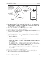
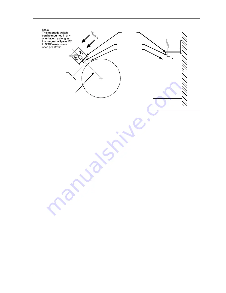
Figure 2-23
. Position Sensor Installation
15.
Wire the switch to SmartPAC PRO terminal block TB5 (see Table 2-11, page 73 and Figure 4 at
the end of the manual). The black wire goes to terminal 247 (GND), the white or clear wire goes
to terminal 246, and the red wire goes to terminal 245.
16.
Power up SmartPAC PRO, and turn the PROG/RUN keyswitch to PROG.
17.
Access the Position Sensor screen again (see steps 4 and 5).
18.
With the highlight bar on the DISABLED setting for the POSITION SENSOR MODE item, press
ENTER to toggle to the ENABLED setting.
19.
Making sure that the magnet is centered beneath the magnetic switch, check the reading next to
the POSITION SENSOR INPUT item. If the reading is ON, go to the next step. If the reading is
OFF, there is a problem. Try the following remedies:
•
Double-check the wiring.
•
Make sure that the ram hasn’t moved since you installed the sensor. If it has, move the ram to
TDC (i.e., 0
) and re-install the magnet (see step 14).
•
If the ram hasn’t moved, check the distance between the magnetic switch and the magnet. Re-
adjust if necessary.
•
If a “Position Sensor Incorrect” error message displays after you try running the press (see
step 22), the position sensor may not have enough dwell to provide an adequate signal at high
speeds. Try mounting the magnet on a smaller shaft (see Figure 2-23).
•
If none of these steps changes the POSITION SENSOR INPUT setting to ON, the magnetic
switch may be bad. Try another switch if one is available. Otherwise, call Wintriss Tech.
Support for help.
20.
Press EXIT and Turn the PROG/RUN keyswitch to RUN.
21.
Inch the press through a few strokes to verify that the position sensor works properly and
SmartPAC PRO does not produce position sensor fault messages.
Gap between
magnet and
magnetic switch:
1/8” to 3/16”
(3.2 to 4.7 mm)
Bracket
attached
to press
Magnetic switch
Magnet location
(Place magnet here
temporarily
to set gap.)
Press
Crankshaft
Crankshaft
Align magnetic
switch with center
of crankshaft
View A
Summary of Contents for SmartPAC PRO
Page 1: ......
Page 2: ......
Page 4: ......
Page 6: ......
Page 20: ......
Page 22: ......
Page 24: ......
Page 42: ...1143100 SmartPAC PRO User Manual 42 Chapter 1 Introduction to SmartPAC PRO ...
Page 142: ...1143100 SmartPAC PRO User Manual 142 Chapter 4 SmartPAC PRO Program Mode ...
Page 200: ...1143100 SmartPAC PRO User Manual 200 Chapter 6 Using DiProPAC Die Protection Optional ...
Page 222: ...1143100 SmartPAC PRO User Manual 222 Chapter 7 ProCamPAC Instructions ...
Page 254: ...1143100 SmartPAC PRO User Manual Appendix C SmartView Remote Viewing and E mail Setup 254 ...
Page 280: ...SmartPAC PRO User Manual 1143100 280 Appendix C Reporting Downtime and Scrap to SFC ...
Page 290: ...SmartPAC PRO User Manual 1143100 290 Index Y yellow fault 232 yellow sensor 169 ...
Page 292: ......
Page 294: ......
Page 296: ......
Page 298: ......
Page 300: ......
Page 301: ......
Page 302: ......
Page 303: ......
Page 304: ......
Page 305: ......
Page 306: ......
Page 307: ......
Page 308: ......
Page 309: ......
Page 310: ......
Page 311: ......
Page 312: ......
Page 313: ......
Page 314: ......
Page 315: ......
Page 316: ......
Page 317: ......
Page 318: ......

