SmartPAC PRO User Manual
1143100
Chapter 5 – SmartPAC PRO Run Mode
149
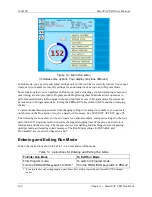
Figure 5-5. Stop Time Status (Brake Monitor) Screen
Stopping time is the time that it takes the crankshaft to stop once the dual safety valve (DSV) has
been de-energized. Starting time is the time it takes for the crankshaft to start turning after the DSV
has been energized. Instructions for setting start time and stop time limits and documentation of
SmartPAC PRO’s responses to start time and stop time faults are provided in
(Optional with WPC 2000 Integration)
Stopping angle is the number of degrees that it takes the press to stop. It is equal to the ram’s stopping
position in degrees minus the crankshaft position when the DSV is de-energized. (Stopping angle
does
not
compensate for the complete rotation of the press when it takes more than 360
to stop.) The
stopping angle value helps you when you set up the top-stop cam. For example, if the stopping angle
is 100
, you would set the top-stop cam to turn on at 260
.
Determining the Stopping Time of Your Press
You need to determine the stopping time of your press at Top Stop in order to calculate the stop time
limit to set in Initialization. To do so, perform the following steps:
1.
Install the heaviest upper die you use on your press. Adjust the counterbalance per the press
manufacturer’s instructions if your press has a counterbalance.
2.
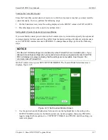
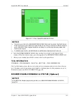
Turn the PROG/RUN keyswitch to RUN to access Run mode, then select BRAKE MONITOR on
the Main Run Menu. The Stop Time Status screen displays.
3.
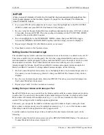
Start the press in Continuous mode, and run the press until it reaches normal operating speed.
4.
Top-stop the press and record the value (in milliseconds) displayed in the STOP TIME VALUE
(MSEC) field.
5.
Repeat steps 3 and 4 five more times. Use the highest stop-time reading from your tests as the
value to use in calculating the stop time limit (see Calculating the Stop Time Limit
page 92).
Summary of Contents for SmartPAC PRO
Page 1: ......
Page 2: ......
Page 4: ......
Page 6: ......
Page 20: ......
Page 22: ......
Page 24: ......
Page 42: ...1143100 SmartPAC PRO User Manual 42 Chapter 1 Introduction to SmartPAC PRO ...
Page 142: ...1143100 SmartPAC PRO User Manual 142 Chapter 4 SmartPAC PRO Program Mode ...
Page 200: ...1143100 SmartPAC PRO User Manual 200 Chapter 6 Using DiProPAC Die Protection Optional ...
Page 222: ...1143100 SmartPAC PRO User Manual 222 Chapter 7 ProCamPAC Instructions ...
Page 254: ...1143100 SmartPAC PRO User Manual Appendix C SmartView Remote Viewing and E mail Setup 254 ...
Page 280: ...SmartPAC PRO User Manual 1143100 280 Appendix C Reporting Downtime and Scrap to SFC ...
Page 290: ...SmartPAC PRO User Manual 1143100 290 Index Y yellow fault 232 yellow sensor 169 ...
Page 292: ......
Page 294: ......
Page 296: ......
Page 298: ......
Page 300: ......
Page 301: ......
Page 302: ......
Page 303: ......
Page 304: ......
Page 305: ......
Page 306: ......
Page 307: ......
Page 308: ......
Page 309: ......
Page 310: ......
Page 311: ......
Page 312: ......
Page 313: ......
Page 314: ......
Page 315: ......
Page 316: ......
Page 317: ......
Page 318: ......


