1143100
SmartPAC PRO User Manual
186
Chapter 6 – Using DiProPAC Die Protection (Optional)
NOTICE
If your press is equipped with hydraulic overload protection, the risk of sticking the press on bottom
is negligible. Selecting E-stop for ALL die-threatening events
– even those that occur between the
critical angle and BDC
– will help to minimize die damage.
To set the stop type for a sensor, do the following:
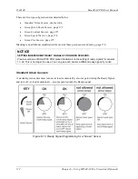
On the Sensor Stop Type screen, select the stop type you want (i.e., EMERGENCY STOP, TOP
STOP, or SMART STOP).
•
If you select SMART STOP and the critical angle has not yet been set, you are taken to the
Critical Angle Programming screen (see next section).
•
If you select EMERGENCY STOP or TOP STOP and the sensor you are programming is a
Green, Green Quick Check, or Green Constant sensor, you are taken to the Ready Signal
Programming screen (see
Setting the Ready Signal for a Green Sensor
•
If you selected EMERGENCY STOP or TOP STOP and the sensor you are programming is a
Green Special sensor, you are taken to the Green Special Sensor Stroke Count screen (see
Setting the Counter Value for a Green Special Sensor
•
If you select EMERGENCY STOP or TOP STOP and the sensor you are programming is a
red or yellow sensor, you are finished, and the Sensor Settings screen displays, on which all
your programmed sensor settings are shown (see
Viewing and Changing Sensor Settings
page 190).
Setting the Critical Angle for a Sensor Set to SMART STOP
When you program a sensor for a Smart Stop, you must also set the critical angle SmartPAC PRO
uses to determine whether an Emergency Stop or Top Stop command is sent to the press. The critical
angle you program for the first sensor set to Smart Stop is used as the critical angle for all sensors set
to Smart Stop for that tool. If you change the Critical Angle setting for one Smart Stop sensor, the
new critical angle is applied to all Smart Stop sensors for that tool.
To set the critical angle for the first sensor set to SMART STOP for a tool, do the following:
1.
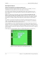
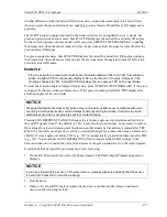
On the Sensor Stop Type screen, select SMART STOP. The Critical Angle Programming screen
displays, Figure 6-31.
2.
Decrement the CRITICAL ANGLE default value of 185
, using the Down (
) cursor key, until
the value you want is displayed. SmartPAC PRO accepts Critical Angle values between 0
and
184
.
3.
Press Enter when you are done.
•
If the sensor you are programming is a Green, Green Quick Check, or Green Constant sensor,
the Ready Signal Programming screen displays (see next section).
•
If the sensor you are programming is a red or yellow sensor, you are finished, and you
are taken to the Sensor Settings screen (see
Viewing and Changing Sensor Settings
, page
Summary of Contents for SmartPAC PRO
Page 1: ......
Page 2: ......
Page 4: ......
Page 6: ......
Page 20: ......
Page 22: ......
Page 24: ......
Page 42: ...1143100 SmartPAC PRO User Manual 42 Chapter 1 Introduction to SmartPAC PRO ...
Page 142: ...1143100 SmartPAC PRO User Manual 142 Chapter 4 SmartPAC PRO Program Mode ...
Page 200: ...1143100 SmartPAC PRO User Manual 200 Chapter 6 Using DiProPAC Die Protection Optional ...
Page 222: ...1143100 SmartPAC PRO User Manual 222 Chapter 7 ProCamPAC Instructions ...
Page 254: ...1143100 SmartPAC PRO User Manual Appendix C SmartView Remote Viewing and E mail Setup 254 ...
Page 280: ...SmartPAC PRO User Manual 1143100 280 Appendix C Reporting Downtime and Scrap to SFC ...
Page 290: ...SmartPAC PRO User Manual 1143100 290 Index Y yellow fault 232 yellow sensor 169 ...
Page 292: ......
Page 294: ......
Page 296: ......
Page 298: ......
Page 300: ......
Page 301: ......
Page 302: ......
Page 303: ......
Page 304: ......
Page 305: ......
Page 306: ......
Page 307: ......
Page 308: ......
Page 309: ......
Page 310: ......
Page 311: ......
Page 312: ......
Page 313: ......
Page 314: ......
Page 315: ......
Page 316: ......
Page 317: ......
Page 318: ......

