1143100
SmartPAC PRO User Manual
54
Chapter 2 – Installing SmartPAC PRO
•
Do not try direct-coupling to the crank because this requires extreme precision. If the resolver is
only slightly off-center, the resolver bearing will be subjected to side loads well beyond its rated
capacity and will ultimately fail.
•
Do not use flexible couplings, which can be inaccurate, or V belts, which may slip and cause
inaccuracy.
•
Do not use a flexible shaft like a speedometer cable. Because the shaft twists on start-up, the
resolver will lag the crank. When the crank stops, the resolver will turn past the true stopping
point and snap backward.
Mounting the Resolver
Once you have thought out your design and gathered the parts, mount the resolver as described
below. Don’t worry about which direction the resolver turns at this point. You will adjust for the
direction of rotation later when you wire the resolver.
1.
Mount the resolver by bolting it to the press or other platform.
2.
Install your drive mechanism.
3.
Make sure the press is within ±5
of Top Dead Center (TDC).
4.
Before attaching the chain or other drive mechanism, rotate the resolver shaft so that the keyway
is aligned with the arrow on the housing. See Figure 2-5.
5.
Keeping the resolver’s keyway aligned with the arrow (within ±5
), attach the chain or drive
mechanism.
Wiring the Resolver
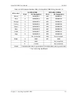
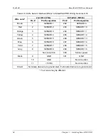
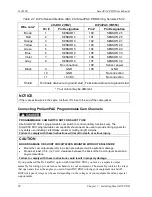
Wire the resolver as follows, referring to Table 2-2, page 55.
1.
Find the resolver cable if it is not connected to the resolver. Plug the end with the connector into
the resolver. It only goes one way. Twist the locknut so the connection is tight.
2.
Run the resolver cable through 1/2 in. conduit from the resolver to the bottom left knockout of the
SmartPAC PRO enclosure.
NOTICE
RUN POSITION SENSOR WIRES WITH RESOLVER WIRES, IF CONVENIENT
If you are installing the position sensor, you can run the position sensor cable through the same
conduit as the resolver wires. Since you cannot install the position sensor until the resolver is
electronically set to 0°, you will have to leave installation of the position sensor until later (see
Installing the Position Sensor (Optional)
, page 78). Refer to Figure 2-23, page 81, for a typical
position sensor mounting location. The position sensor is usually placed near the resolver.
3.
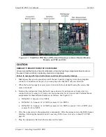
Find the resolver connector TB-3 on the SmartPAC PRO board (see Figure 2-6
page 53).
4.
Measure and cut the resolver wires so they comfortably reach SMARTPAC PRO. (If you run the
position sensor cable through the same conduit, do not cut these wires until the position sensor is
installed).
5.
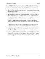
Viewing the resolver from the shaft end, determine which direction the shaft will turn – clockwise
Summary of Contents for SmartPAC PRO
Page 1: ......
Page 2: ......
Page 4: ......
Page 6: ......
Page 20: ......
Page 22: ......
Page 24: ......
Page 42: ...1143100 SmartPAC PRO User Manual 42 Chapter 1 Introduction to SmartPAC PRO ...
Page 142: ...1143100 SmartPAC PRO User Manual 142 Chapter 4 SmartPAC PRO Program Mode ...
Page 200: ...1143100 SmartPAC PRO User Manual 200 Chapter 6 Using DiProPAC Die Protection Optional ...
Page 222: ...1143100 SmartPAC PRO User Manual 222 Chapter 7 ProCamPAC Instructions ...
Page 254: ...1143100 SmartPAC PRO User Manual Appendix C SmartView Remote Viewing and E mail Setup 254 ...
Page 280: ...SmartPAC PRO User Manual 1143100 280 Appendix C Reporting Downtime and Scrap to SFC ...
Page 290: ...SmartPAC PRO User Manual 1143100 290 Index Y yellow fault 232 yellow sensor 169 ...
Page 292: ......
Page 294: ......
Page 296: ......
Page 298: ......
Page 300: ......
Page 301: ......
Page 302: ......
Page 303: ......
Page 304: ......
Page 305: ......
Page 306: ......
Page 307: ......
Page 308: ......
Page 309: ......
Page 310: ......
Page 311: ......
Page 312: ......
Page 313: ......
Page 314: ......
Page 315: ......
Page 316: ......
Page 317: ......
Page 318: ......

