SmartPAC PRO User Manual
1143100
Chapter 2 – Installing SmartPAC PRO
55
or counterclockwise – when the press runs.
6.
Unplug the L-shaped connector from TB3.
NOTICE
WIRE AND PLUG IN CONNECTOR CORRECTLY
The connector can plug into the receptacle on the PC board in only one direction. Before wiring the
connector, mark its left and right ends when it is plugged in to make sure you wire the correct pin
numbers.
7.
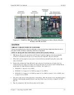
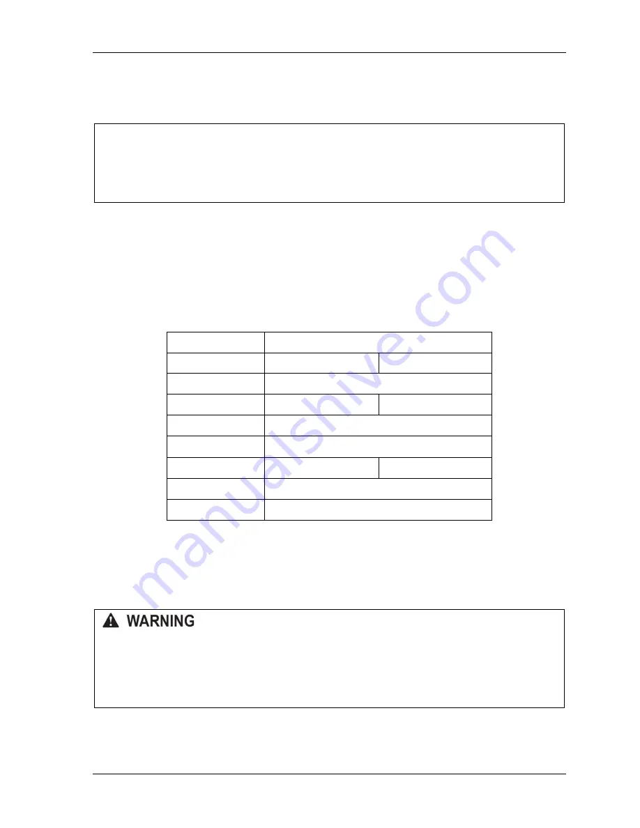
Connect the wires to TB3 as shown in Table 2-2. Make sure you connect the black and yellow
wires correctly, based upon the way your resolver will rotate – clockwise or counterclockwise –
as you face the resolver shaft.
8.
Double-check connections when you are finished wiring.
9.
Plug the L-shaped connector firmly into its receptacle on the SmartPAC PRO board. It can plug
in only one way.
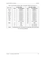
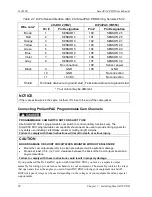
Table 2-2
. Resolver Wiring
Resolver Cable Wire Color
Pin # on TB3
CW Rotation
CCW Rotation
212 (GND)
No connection
213 (S1)
Black
Yellow
214 (S2)
Green
215 (R1)
Red
216 (S3)
Yellow
Black
217 (R2)
Orange
218 (S4)
Brown
Terminate the cable shield to the ground stud nearest the
cable entry.
Connecting Power Wiring
– AC Powered Units
ELECTRIC SHOCK HAZARD
•
Do not connect the AC power source until you are done with all other installation procedures.
•
Turn off and disconnect power from the machinery SmartPAC PRO is connected to before
making any wiring connections. This includes power to the machine control and motor.
Failure to comply with these instructions could result in death or serious injury.
Run the AC power wires through a “high-voltage” conduit (see
page 45)
along with the wiring for emergency-stop, top-stop, and input check circuits. No. 16 wire (No. 14, if
Summary of Contents for SmartPAC PRO
Page 1: ......
Page 2: ......
Page 4: ......
Page 6: ......
Page 20: ......
Page 22: ......
Page 24: ......
Page 42: ...1143100 SmartPAC PRO User Manual 42 Chapter 1 Introduction to SmartPAC PRO ...
Page 142: ...1143100 SmartPAC PRO User Manual 142 Chapter 4 SmartPAC PRO Program Mode ...
Page 200: ...1143100 SmartPAC PRO User Manual 200 Chapter 6 Using DiProPAC Die Protection Optional ...
Page 222: ...1143100 SmartPAC PRO User Manual 222 Chapter 7 ProCamPAC Instructions ...
Page 254: ...1143100 SmartPAC PRO User Manual Appendix C SmartView Remote Viewing and E mail Setup 254 ...
Page 280: ...SmartPAC PRO User Manual 1143100 280 Appendix C Reporting Downtime and Scrap to SFC ...
Page 290: ...SmartPAC PRO User Manual 1143100 290 Index Y yellow fault 232 yellow sensor 169 ...
Page 292: ......
Page 294: ......
Page 296: ......
Page 298: ......
Page 300: ......
Page 301: ......
Page 302: ......
Page 303: ......
Page 304: ......
Page 305: ......
Page 306: ......
Page 307: ......
Page 308: ......
Page 309: ......
Page 310: ......
Page 311: ......
Page 312: ......
Page 313: ......
Page 314: ......
Page 315: ......
Page 316: ......
Page 317: ......
Page 318: ......


