1143100
SmartPAC PRO User Manual
56
Chapter 2 – Installing SmartPAC PRO
local codes require it) with a minimum 75
C temperature rating is recommended for these circuits.
Bring the conduit into the top right knockout of the SmartPAC PRO enclosure. Then, to wire the AC
input terminal block, follow these steps:
1.
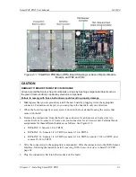
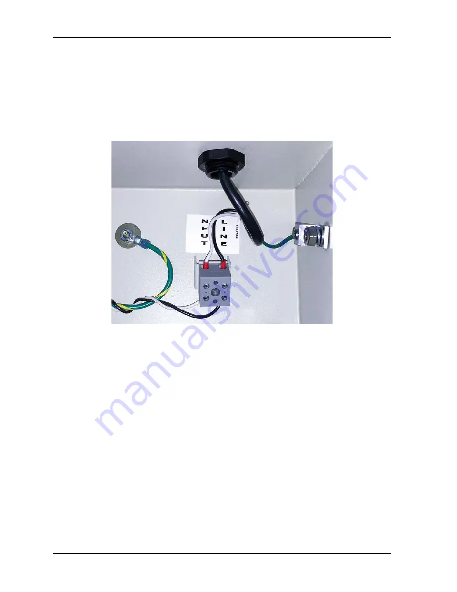
Find the AC terminal block at the top right corner of the back wall of the enclosure (see Figure
2-7).
For a panel mount unit, the terminal block is mounted to the back of the faceplate near the top
right corner of the SmartPAC PRO PC board.
Figure 2-7
. Wiring AC to Terminal Block, Inside Enclosure, Top Right
2.
Determine how you will bring wiring from your 115 Vac power source (or 230V source, if
applicable) to the unit. These wires should be connected directly to the press control transformer
at the press control. For 115 Vac, you need three wires: high (black), neutral
(white) and ground
(green). For 230 Vac, wires are black and red with green or green/ yellow for ground.
3.
Connect the AC input wires and ground wire as shown in Figure 2-7 and Figure 4 at the back of
the manual. Make your ground connection as follows:
•
SmartPAC PRO Enclosure
: Connect your ground (green or green/yellow) wire to the set
screw terminal on the inside of the enclosure. To connect to the set screw terminal, strip the
ground wire about 1/4 in. (6.4 mm) from end, loosen the screw on the terminal, slide the wire
in the hole, and tighten the screw to secure the wire in place.
•
SmartPAC PRO Panel Mount
: Connect the ground wire to the ground stud on the face plate
below the AC input terminal block.
4.
Connect AC wires to the power source only after all installation procedures have been completed
and you are ready to perform final checkout tests (see page 82).
Summary of Contents for SmartPAC PRO
Page 1: ......
Page 2: ......
Page 4: ......
Page 6: ......
Page 20: ......
Page 22: ......
Page 24: ......
Page 42: ...1143100 SmartPAC PRO User Manual 42 Chapter 1 Introduction to SmartPAC PRO ...
Page 142: ...1143100 SmartPAC PRO User Manual 142 Chapter 4 SmartPAC PRO Program Mode ...
Page 200: ...1143100 SmartPAC PRO User Manual 200 Chapter 6 Using DiProPAC Die Protection Optional ...
Page 222: ...1143100 SmartPAC PRO User Manual 222 Chapter 7 ProCamPAC Instructions ...
Page 254: ...1143100 SmartPAC PRO User Manual Appendix C SmartView Remote Viewing and E mail Setup 254 ...
Page 280: ...SmartPAC PRO User Manual 1143100 280 Appendix C Reporting Downtime and Scrap to SFC ...
Page 290: ...SmartPAC PRO User Manual 1143100 290 Index Y yellow fault 232 yellow sensor 169 ...
Page 292: ......
Page 294: ......
Page 296: ......
Page 298: ......
Page 300: ......
Page 301: ......
Page 302: ......
Page 303: ......
Page 304: ......
Page 305: ......
Page 306: ......
Page 307: ......
Page 308: ......
Page 309: ......
Page 310: ......
Page 311: ......
Page 312: ......
Page 313: ......
Page 314: ......
Page 315: ......
Page 316: ......
Page 317: ......
Page 318: ......


