1143100
SmartPAC PRO User Manual
58
Chapter 2 – Installing SmartPAC PRO
Making Wiring Connections
To make wiring connections from SmartPAC PRO to your press control emergency-stop, top- stop,
and input check circuits, do the following:
1.
Run the stop circuit and input check circuit wires to SmartPAC PRO through flexible liquid- tight
conduit to the enclosure. Because SmartPAC PRO is rated NEMA 12 (protected against dust and
oil), you must use conduit of the same rating and make proper connections to ensure that the
enclosure is NEMA-12-protected.
2.
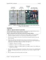
Locate connector TB4 on the SmartPAC PRO board (see Figure 2-11
page 61) and unplug it
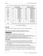
from its socket. Connect the wires for the stop and input check circuits to TB4 pin locations, as
shown in Table 2-3 and wiring diagram Figure 4 at the end of the manual.
Table 2-3
. Stop and Input Check Circuit Wiring Connections: TB4
Circuit
SmartPAC PRO TB 4
Pin Locations
Input check A
205
Input check B
206
E-stop
207
E-stop
208
Top-stop
209
Top-stop
210
3.
Plug the connector back into its socket. Double-check connections to make sure that you did not
wire the connector backward.
4.
Connect top-stop, E-stop, and input check circuit wires at the press control or other box into
which you are tying them.
NOTICE
Be
sure to number all wires in a way consistent with your press’s electrical prints.
5.
Make all the necessary conduit connections to ensure NEMA 12 protection.
Setting the Input Check Voltage Switch
To set voltage for the input check circuit, do the following:
1.
Find the input check voltage switch, S101, on the SmartPAC PRO board. It is located on the right
side of the board just to the left of the E-stop relays.
2.
Place S101 in the Left or Right position, depending on the coil voltage of the dual safety valve.
For a coil voltage of 60-250V, place the switch in the Left position (this is the factory setting).
For 12-60V coil voltage, set the switch to the Right setting (Figure 2-9).
Summary of Contents for SmartPAC PRO
Page 1: ......
Page 2: ......
Page 4: ......
Page 6: ......
Page 20: ......
Page 22: ......
Page 24: ......
Page 42: ...1143100 SmartPAC PRO User Manual 42 Chapter 1 Introduction to SmartPAC PRO ...
Page 142: ...1143100 SmartPAC PRO User Manual 142 Chapter 4 SmartPAC PRO Program Mode ...
Page 200: ...1143100 SmartPAC PRO User Manual 200 Chapter 6 Using DiProPAC Die Protection Optional ...
Page 222: ...1143100 SmartPAC PRO User Manual 222 Chapter 7 ProCamPAC Instructions ...
Page 254: ...1143100 SmartPAC PRO User Manual Appendix C SmartView Remote Viewing and E mail Setup 254 ...
Page 280: ...SmartPAC PRO User Manual 1143100 280 Appendix C Reporting Downtime and Scrap to SFC ...
Page 290: ...SmartPAC PRO User Manual 1143100 290 Index Y yellow fault 232 yellow sensor 169 ...
Page 292: ......
Page 294: ......
Page 296: ......
Page 298: ......
Page 300: ......
Page 301: ......
Page 302: ......
Page 303: ......
Page 304: ......
Page 305: ......
Page 306: ......
Page 307: ......
Page 308: ......
Page 309: ......
Page 310: ......
Page 311: ......
Page 312: ......
Page 313: ......
Page 314: ......
Page 315: ......
Page 316: ......
Page 317: ......
Page 318: ......

