1143100
SmartPAC PRO User Manual
78
Chapter 2 – Installing SmartPAC PRO
0
, preferably between 355
and 5
, but anywhere between 330
and 30
is acceptable.
If the current resolver angle is outside the range of 330
to 30
, loosen the tension on your drive
mechanism and turn the resolver shaft by hand (either direction is acceptable) until the resolver
angle is as close to zero as possible. Then tighten the drive mechanism, making sure not to
change the resolver angle reading.
3.
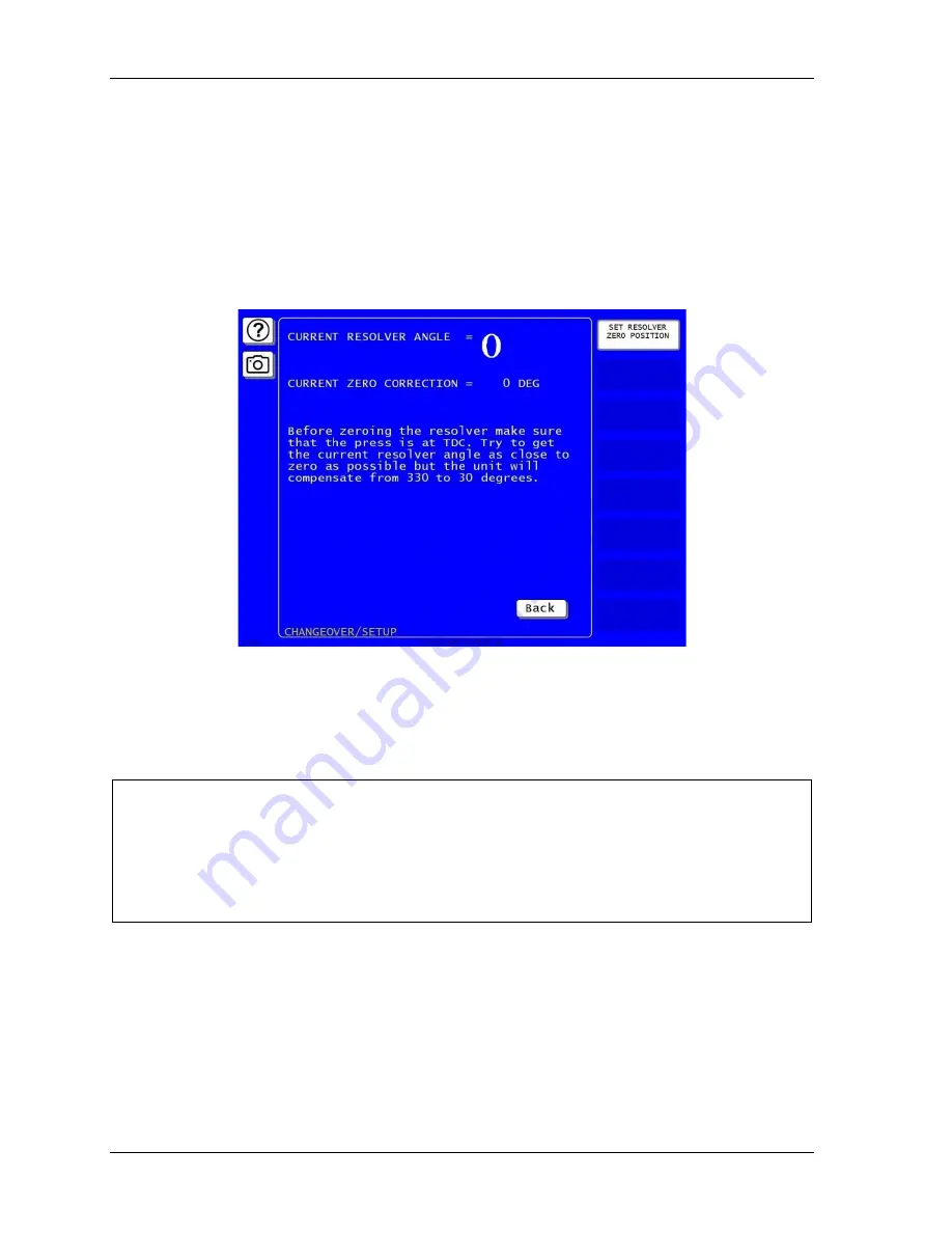
With the Resolver Zero display on the screen, press SET RESOLVER ZERO POSITION.
SmartPAC PRO electronically adds or subtracts the offset, and the CURRENT ZERO
CORRECTION reading should change to match CURRENT RESOLVER ANGLE.
Figure 2-20
. “Resolver Zero” Screen
4.
Press Exit when you are finished. You are returned to the Main Initialization Menu.
Installing the Position Sensor (Optional)
CAUTION
MISALIGNMENT OF RESOLVER AND CRANKSHAFT
If you have installed the position sensor, enable it during initialization and leave it enabled even
though it is optional for SmartPAC PRO operation. If you disable the position sensor to clear an
error message, misalignment between the resolver and crankshaft will go undetected.
Failure to comply with these instructions could result in property damage.
The position sensor is an optional feature that allows position of the resolver to be checked on every
stroke. This feature consists of a magnet, which is usually mounted on the crankshaft, and a magnetic
switch, which is mounted on a stationary part of the press past which the magnet passes as the
crankshaft turns. The magnetic switch must be mounted so that it senses the magnetic field at the
same point on every stroke.
SmartPAC PRO compares the timing of this signal with the angle of the resolver. If the resolver angle
changes relative to this signal, SmartPAC PRO knows that the resolver drive has slipped or broken or
Summary of Contents for SmartPAC PRO
Page 1: ......
Page 2: ......
Page 4: ......
Page 6: ......
Page 20: ......
Page 22: ......
Page 24: ......
Page 42: ...1143100 SmartPAC PRO User Manual 42 Chapter 1 Introduction to SmartPAC PRO ...
Page 142: ...1143100 SmartPAC PRO User Manual 142 Chapter 4 SmartPAC PRO Program Mode ...
Page 200: ...1143100 SmartPAC PRO User Manual 200 Chapter 6 Using DiProPAC Die Protection Optional ...
Page 222: ...1143100 SmartPAC PRO User Manual 222 Chapter 7 ProCamPAC Instructions ...
Page 254: ...1143100 SmartPAC PRO User Manual Appendix C SmartView Remote Viewing and E mail Setup 254 ...
Page 280: ...SmartPAC PRO User Manual 1143100 280 Appendix C Reporting Downtime and Scrap to SFC ...
Page 290: ...SmartPAC PRO User Manual 1143100 290 Index Y yellow fault 232 yellow sensor 169 ...
Page 292: ......
Page 294: ......
Page 296: ......
Page 298: ......
Page 300: ......
Page 301: ......
Page 302: ......
Page 303: ......
Page 304: ......
Page 305: ......
Page 306: ......
Page 307: ......
Page 308: ......
Page 309: ......
Page 310: ......
Page 311: ......
Page 312: ......
Page 313: ......
Page 314: ......
Page 315: ......
Page 316: ......
Page 317: ......
Page 318: ......

