1143100
SmartPAC PRO User Manual
82
Chapter 2 – Installing SmartPAC PRO
22.
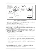
Inch the press while watching the Position Sensor LED, located beneath the Input Check Voltage
Switch on the SmartPAC PRO board. Stop the press when the LED comes ON and make a note
of the ON angle. Continue to inch the press until the LED goes OFF, and make a note of the OFF
angle. The sensor should be ON at 0
, and, preferably, 0
should occur at the midpoint of the ON
period.
NOTICE
Do not use a ferrous screw to mount the position sensor. A ferrous screw can cause false signals.
23.
If the position sensor appears to be working properly, permanently mount the magnet, plastic side
up, using a non-ferrous metal screw. A brass screw (6-32) is supplied. Use a No. 36 drill and a
6-32 tap.
Final Checkout
Before using SmartPAC PRO, you need to follow these instructions to ensure that your unit is
working properly. Do not proceed to the next step or group of steps until the item you are testing
checks out.
Set Up a “Test” Tool
1.
Create a “Test” tool, following the steps in
2.
Enter a counter preset of 10,000 for the tool, following the directions in
3.
Load the tool, following the instructions in
, page 130, then turn the PROG/RUN
keyswitch to RUN.
Check and Set Direction of Rotation of Resolver
4.
Inch the press. Watch the crankshaft angle reading inside the crank angle clock at the lower left
of the display. The crankshaft angle should increase as you inch the press. If it decreases (359
,
358
, 357
, for example), swap the black wire and yellow wire (terminals 213 and 216) on
connector TB3 on the SmartPAC PRO board (see Table 2-2, page 55).
Check for Position Sensor (If Installed) Error Messages
5.
If a position sensor is installed and a position sensor fault occurs, refer to step 19 of the procedure
in Installing the Position Sensor (Optional), page 78. For other error messages, go to
and follow the instructions for solving the specific problem. When you have corrected the error,
press RESET and run the press again for a few strokes, checking for error messages.
•
If no error messages display, go to step 6.
•
If error messages continue to display, and you cannot correct the fault, call Wintriss Tech.
Support.
Check the Top-stop Circuit
6.
Set the stroke counter preset to a small value (e.g., 10), referring to
run the press in continuous mode until the preset value is reached. Check to make sure that the
press top-stops and that a message indicating that the preset was reached is displayed (see
Summary of Contents for SmartPAC PRO
Page 1: ......
Page 2: ......
Page 4: ......
Page 6: ......
Page 20: ......
Page 22: ......
Page 24: ......
Page 42: ...1143100 SmartPAC PRO User Manual 42 Chapter 1 Introduction to SmartPAC PRO ...
Page 142: ...1143100 SmartPAC PRO User Manual 142 Chapter 4 SmartPAC PRO Program Mode ...
Page 200: ...1143100 SmartPAC PRO User Manual 200 Chapter 6 Using DiProPAC Die Protection Optional ...
Page 222: ...1143100 SmartPAC PRO User Manual 222 Chapter 7 ProCamPAC Instructions ...
Page 254: ...1143100 SmartPAC PRO User Manual Appendix C SmartView Remote Viewing and E mail Setup 254 ...
Page 280: ...SmartPAC PRO User Manual 1143100 280 Appendix C Reporting Downtime and Scrap to SFC ...
Page 290: ...SmartPAC PRO User Manual 1143100 290 Index Y yellow fault 232 yellow sensor 169 ...
Page 292: ......
Page 294: ......
Page 296: ......
Page 298: ......
Page 300: ......
Page 301: ......
Page 302: ......
Page 303: ......
Page 304: ......
Page 305: ......
Page 306: ......
Page 307: ......
Page 308: ......
Page 309: ......
Page 310: ......
Page 311: ......
Page 312: ......
Page 313: ......
Page 314: ......
Page 315: ......
Page 316: ......
Page 317: ......
Page 318: ......


