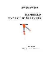
background image

BW20/BW20S

HANDHELD

HYDRAULIC BREAKERS

USER MANUAL

Safety, Operation and Maintenance

Summary of Contents for BW20

Page 1: ...BW20 BW20S HANDHELD HYDRAULIC BREAKERS USER MANUAL Safety Operation and Maintenance ...

Page 2: ...ULIC EQUIPMENT 6 OPERATION 7 i PREPARATIONS BEFORE OPERATION 7 ii CHECK POWER SOURCE 7 iii CHECK TOOL 7 iv CHECK TIGGER 7 v CONNECT HOSES 7 CHARGING THE ACCUMULATOR 8 TROUBLESHOOTING 10 SPECIFICATIONS 11 ACCESSORIES 12 BW18 T HANDLE ILLUSTRATION 12 BW18 T HANDLE PARTS LIST 13 BW18S ANTI VIB ILLUSTRATION 16 BW18S ANTI VIB PARTS LIST 17 WARRANTY 20 MAINTENANCE RECORDS 21 ...

Page 3: ...anders The operator must be familiar with all prohibited work areas such as excessive slopes and dangerous terrain conditions Establish a training program for all operators to ensure safe operation Do not operate the tool unless thoroughly trained or under the supervision of an instructor Always wear safety equipment such as goggles gloves ear head and breathing protection and safety shoes at all ...

Page 4: ...le injury or death CAUTION This is the safety alert symbol It is used to alert you to potential personal injury hazards Obey all safety messages that follow this symbol to avoid possible injury or death Safety symbols and signal words are used to emphasize all operation maintenance and repair actions which if not strictly followed could result in a life threatening situation bodily injury or damag...

Page 5: ...re may cause a leak or burst b Do not exceed rated working pressure of hydraulic hose used with this tool Excess pressure may cause a leak or burst c Check tool hose couplers and connectors daily for leaks Do not feel for leaks with your hands Contact with a leak may result in severe personal injury Important d Do not lift or carry tool by the hoses Do not abuse hose Do not use kinked torn or dama...

Page 6: ...brasions bulges or damage to couplings if any of these conditions exist replace the hose immediately Never use tape or any device to attempt to mend the hose 6 After each use store in a clean dry area THE TAG SHOWN BELOW IS ATTACHED TO CONDUCTIVE HOSE DANGER 1 Do not use this hydraulic hose on or near electric lines 2 For proper and safe operation make sure that you have been properly trainedin co...

Page 7: ...ecommended by WIPIN Hydraulic Tools 7 Supply hoses must have a minimum working pressure rating of 2500 psi 175 bar 8 There must be a filter it can filter the min size 25μm impurity 9 Establish a training program for all operators to ensure safe operation 10 Be sure all joint are dry especially before work 11 On the request working temperature the viscosity of hydraulic oil must between 20 82cts 12...

Page 8: ...hin the tool 3 Observe flow indicators stamped on hose couplers to ensure that fluid flow is in the proper direction The female coupler on the tool hose is the inlet coupler NOTE If uncoupled hoses are left in the sun pressure increase within the hoses may make them difficult to connect When possible connect the free ends of the hoses together OPERATION PROCEDURES 1 Observe all safety precautions ...

Page 9: ...8 CHARGING THE ACCUMULATOR Charging Tools There are two parts 1 control assembly 2 ACCUMULATOR TESTER 3 Connection pic ...

Page 10: ...s maximum 4 Open the nitrogen tank Adjust the snub valve to a chargingpressure 5 Check the data of gauge got the proper charge pressure 6 unscrew the entire tester assembly from the accumulator charging valve turn the gauge fully counterclockwise to ensure that the stem inside the chuck is completely retracted Then turn the gauge fully clockwise and watching the pressure gauge if the data are not ...

Page 11: ...ely Power unit not functioning Check power unit for power flow and pressure 15 24 lpm 105 140 bar Couplers or hoses blocked Remove restriction Fluid too hot above 140 F 60 C Provide cooler to maintain proper fluid temperature 130 F 55 C Low accumulator charge pressure hose will pulse more than normal Recharge accumulator Replace diaphragm if charge loss continues Tool operates slow Low gpm supply ...

Page 12: ...ONS Weight 20kg Length 60cm Width 35cm Pressure range 105 140bar Flow range 7 9gpm 26 34lpm Normal flow 8gpm 30lpm Connect Size Type 3 8 in Male Pipe Hose Ends System Type Open or Closed Center Port Size SAE 8 O ring ...

Page 13: ...12 BW18 T HANDLE ILLUSTRATION ...

Page 14: ...WHIP 9030004004 2 15 COUPLER 9010207001 1 16 COUPLER 9010207002 1 17 PUSH PIN 9020013003 2 18 AUTOMATIC VALVE 004A000005 1 19 PISTON 004A000006 2 20 AUTOMATIC VALVE BODY 004A000007 1 21 BACK UP RING 9020009003 2 22 Valve plate 004A000008 1 23 O RING 9020006005 2 24 tag 004A000031 1 25 tag 004A000032 1 26 ACCUMULATOR ON OFF VALVE BLOCK 004A000009 1 27 tag 004A000033 1 28 tag 004A000034 1 29 ACCUMUL...

Page 15: ...D WIPER 9020006007 1 41 BACK UP WASHER 004A000020 1 42 U RING 9020006008 1 43 SIDE ROD 004B000005 4 44 latch handle 004A000022 1 45 SPRING WASHER 9020004007 2 46 FOOT LATCH BOLT 9020001024 1 47 RUBBER SLEEVE 004A000023 2 48 Spring 9020010003 1 49 DETENT 9020013002 1 ...

Page 16: ... 1 8 O RING 9020006003 1 10 U RING 9020006004 1 21 BACK UP RING 9020006003 2 23 O RING 9020006005 2 39 O RING 9020006006 1 40 Dust ring ROD WIPER 9020006007 1 42 U RING 9020006008 1 Pickaxe ITEM NAME P N QTY SPECIFICATION 1 Sharp Pickaxe 004A000041 1 2 Flat Pickaxe 004A000042 1 ...

Page 17: ...16 BW18S ANTI VIB ILLUSTRATION ...

Page 18: ...2 15 COUPLER 9010207001 1 16 COUPLER 9010207002 1 17 PUSH PIN 9020013003 2 18 AUTOMATIC VALVE 004A000005 1 19 PISTON 004A000006 2 20 AUTOMATIC VALVE BODY 004A000007 1 21 BACK UP RING 9020009003 2 22 Valve plate 004A000008 1 23 O RING 9020006005 2 24 tag 004A000031 1 25 tag 004A000032 1 26 ACCUMULATOR ON OFF VALVE BLOCK 004A000009 1 27 tag 004A000033 1 28 tag 004A000034 1 29 ACCUMULATOR DIAPHRAGM 9...

Page 19: ... 9020003009 1 44 BREAKER FOOT ASSY 004A000019 1 45 O RING 9020006006 1 46 ROD WIPER 9020006007 1 47 BACK UP WASHER 004A000020 1 48 U RING 9020006008 1 49 SIDE ROD 004A000021 4 50 latch handle 004A000022 1 51 SPRING WASHER 9020004007 2 52 FOOT LATCH BOLT 9020001024 1 53 RUBBER SLEEVE 004A000023 2 54 Spring 9020010003 1 55 DETENT 9020013002 1 ...

Page 20: ... 1 8 O RING 9020006003 1 10 U RING 9020006004 1 21 BACK UP RING 9020006003 2 23 O RING 9020006005 2 45 O RING 9020006006 1 46 Dust ring ROD WIPER 9020006007 1 48 U RING 9020006008 1 Pickaxe ITEM NAME P N QTY SPECIFICATION 1 Sharp Pickaxe 004A000041 1 2 Flat Pickaxe 004A000042 1 ...

Page 21: ...ories Sealing Element The warranty of sealing element is 6 months from the date of working free maintain won t be given under the following circumstance The damage caused by Incorrect Replacing and installing The damage caused by Incorrect store and move The damage caused by Incorrect operation The damage caused by Incorrect maintenance The damage caused by Incorrect Repair The damage caused by ac...

Page 22: ...e NO Model Product Series Date of purchasing Seller s company Address City Post code Hydraulic tool Tool s name or model Product Recording Card Model Product series Date of purchasing Seller s company Address Post code Telephone No Fax Note MAINTENANCE RECORDS 21 ...

Reviews: