Wireless Sensors, LLC
Ethernet Gateway Model GWAY-1100
Version 2.0 © July 2013
12 / 35
Basic 1-Wire Device Information
o
Description
—the description of the device
1
o
ROM ID
—the unique number assigned to each 1-Wire device
o
Device
—the name of the device
o
Channel
—the channel the device is connected to
o
Health
—the health of the device. Each time a device is successfully read, its
health field is incremented by 1, to a maximum value of 7. If a device fails to read
properly for any reason, its health field is decremented by 1, to a minimum value of
0. Generally, a health value of 7 indicates a properly functioning device, 0 indi-
cates a device that has been disconnected, and anything in between might indi-
cate intermittent communication or a recently connected device.
o
Value
—the primary value of the sensor on the connected device
During normal operation the GWAY-1100 automatically scans the 1-Wire bus in the following or-
der:
Searches for devices
—if new devices are found, they are added to the end of the de-
vice list
2
Reads data
—each sensor is read and fields are updated before proceeding to next sen-
sor
English/Metric Conversion
Select the Metric or English system of measurement. The page will refresh to display the data in
the system of your choice.
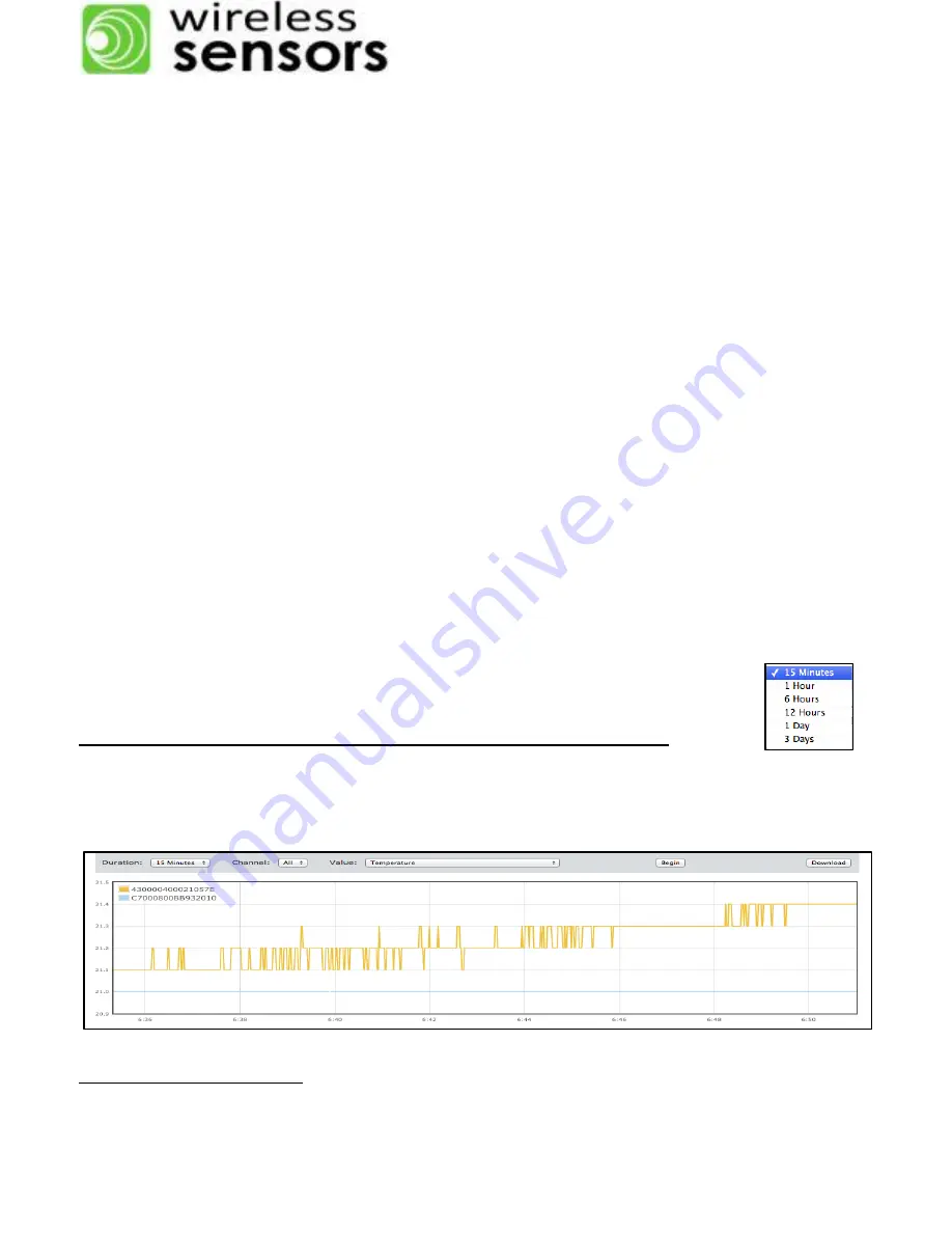
Graph
On the
Home
page, a single value of all devices connected to a one, or all channels of the
GWAY-1100 can be graphed. The duration of the graph window ranges from 15 minutes to 3
days. Select the appropriate variable; press begin.
Graphing will not start until
the Begin button is selected.
Data is not stored - if you leave the Web page, the graph will be lost.
You can
open multiple Web pages to view additional information, however each additional
Web page browser will slow the response from the GWAY-1100.
Download
1
Please note that the description is commonly based on the Maxim IC, not the sensor type (i.e. humidity, light,
barometric pressure) connected to the chip.
2
The order of devices in the list may change if the power is cycled.


