background image


Revision 4 
Author: Anders Zellén 
 

Wireless Solution Sweden Sales AB 

Stureparksvägen 7 

– 451 55 Uddevalla – Sweden 

+46 522 511 511 Tel. +46 522 440 885 Fax. 

Wirelessdmx.com    sales@wirelessdmx.com 

1(23)


14/11/2014 


W-DMX TRX 


IMPLEMENTATION GUIDE 

L6 GENERATION 4S 


REV. 4 


Pro L6 


Summary of Contents for W-DMX TRX

Page 1: ...én Wireless Solution Sweden Sales AB Stureparksvägen 7 451 55 Uddevalla Sweden 46 522 511 511 Tel 46 522 440 885 Fax Wirelessdmx com sales wirelessdmx com 1 23 14 11 2014 W DMX TRX IMPLEMENTATION GUIDE L6 GENERATION 4S REV 4 Pro L6 ...

Page 2: ...ficial standard for Wireless DMX and RDM control The G4S line contains the following key features 1 Support for Adaptive Frequency Hopping Spread Spectrum technology This technology allows the system to dynamically avoid other users of the radio spectrum in order to ensure that we do not cause interference with other radio users i e WLAN All radio cards come with this functionality as standard wit...

Page 3: ...Any disclosure copying distribution or use of the contents of the information herein without prior written authorization from Wireless Solution is prohibited Please refer to our Non Disclosure Agreement for complete information about Wireless Solution s confidentiality and non disclosure policies Warning ESD sensitive device The W DMX PCB is sensitive to ESD Follow proper ESD control procedures wh...

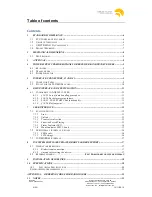
Page 4: ...FORMITY TO ANSI E1 11 2008 11 6 1 1 10 5 3 Loss of data handling procedure 11 6 1 2 10 5 4 Packet processing latency 11 6 1 3 10 5 5 NULL START Code functionality 12 6 1 4 10 5 6 Slot footprint 12 7 USER INTERFACE 12 7 1 FUNCTION SWITCH 12 7 1 1 Link 12 7 1 2 Unlink 12 7 1 3 Transceiver direction 12 7 1 4 Function Switch Timing 12 7 1 5 Status Indicator LED 14 7 1 6 Mode Indicator LED L6 only 15 7...

Page 5: ...Revision 4 Author Anders Zellén Wireless Solution Sweden Sales AB Stureparksvägen 7 451 55 Uddevalla Sweden 46 522 511 511 Tel 46 522 440 885 Fax Wirelessdmx com sales wirelessdmx com 5 23 14 11 2014 ...

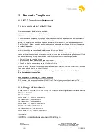
Page 6: ...s equipment does cause harmful interference to radio or television reception which can be determined by turning the equipment off and on the user is encouraged to try and correct the interference by one or more of the following measures Reorient or locate the receiving antenna Increase the separation between the equipment and receiver Connect the equipment into an outlet on a circuit different fro...

Page 7: ...2 440 885 Fax Wirelessdmx com sales wirelessdmx com 7 23 14 11 2014 1 3 USITT DMX 512 A Compliance This device complies with the USITT DMX 512A standard as described in ANSI E1 11 2008 See section 6 1 for details 1 4 Product Marking The following text must be added to the host product for the USA market Contains FCC ID NY2 WDMXTRXDB ...

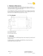
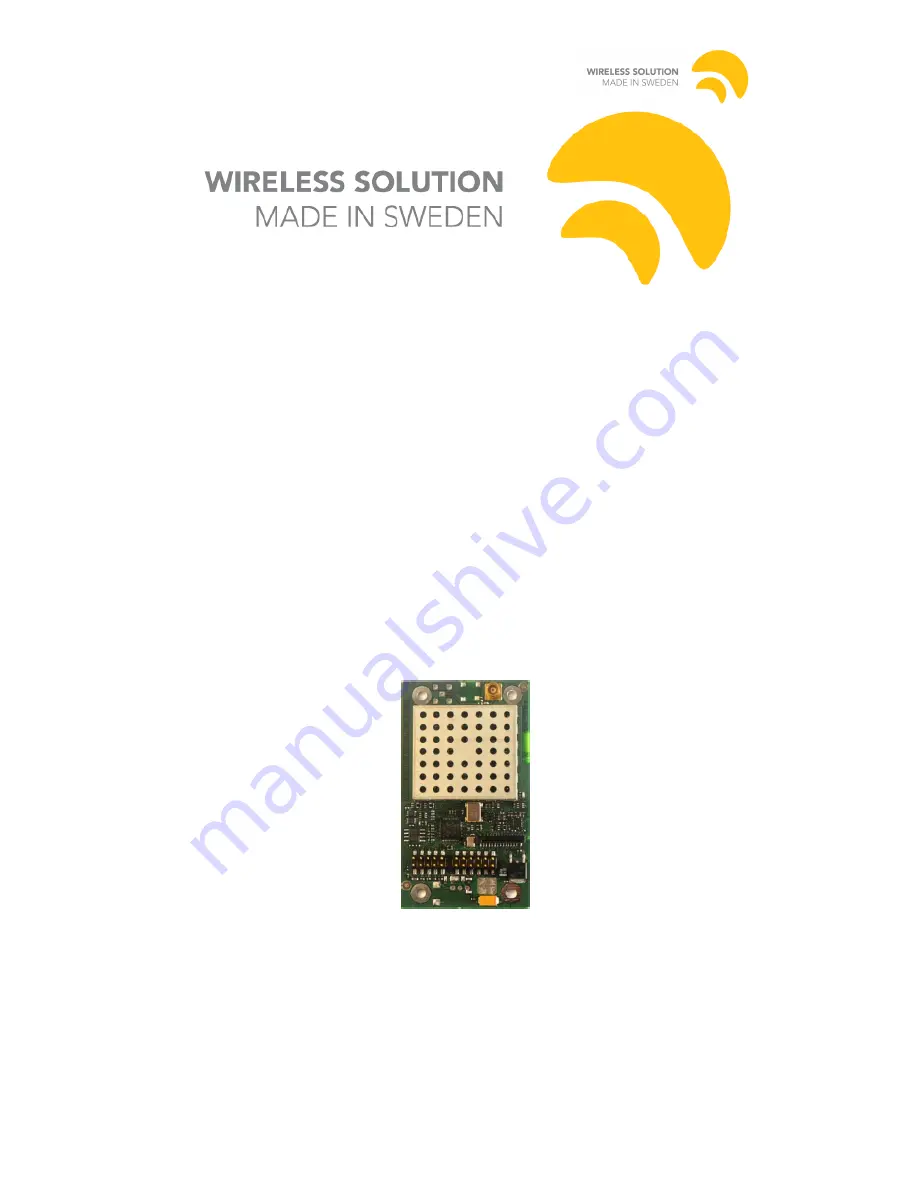
Page 8: ...y and are thus not equipped with this shield Auto Cad DXF files with file with relevant dimensions are available on request from Wireless Solution The total height of Pro cards is 11 mm the highest point it the pin header take into consideration the receptacle that you choose 2 1 Pro L6 model S2 S3 and S4 is M3 holes S1 is a slot 3 9 x 3 1 mm X2 is the antenna connector 3 Antennas Note that severa...

Page 9: ...X cards have built in under voltage detection which protects the system from permanent electrical damage but data loss might still occur If the transceiver card is used as an RDM receiver then you also need to take into consideration the current used during transmission 4 3 Power Indicator The W DMX card is equipped with an on board green Power Indicator LED which is lit when the card is powered p...

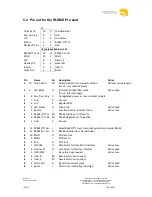
Page 10: ...tive High J1 8 Pwr Non Reg P Unregulated power in only on select models J1 7 Gnd P Ground J1 6 5V P Regulated 5V J1 5 LED Status O Status Led Active High J1 4 Button I Function Button Internal Pullup Active Low J1 3 RS485 TTL Tx I O RS485 Positive or TTL level Tx J1 2 RS485 TTL Rx I O RS485 Negative or TTL level Rx J1 1 Gnd P Ground J3 12 RS485 TTL Sel I Select RS485 TTL level Internally pulled lo...

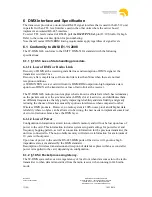
Page 11: ...protocol employs what is known as Data Safe which has redundancy on the packets sent over the air and send each DMX slot at least twice and distributes them on different frequencies thereby greatly improving reliability and data fidelity and greatly reducing the chance of data loss caused by spurious interference when compared to other Wireless DMX products However no radio system is 100 noise pro...

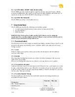
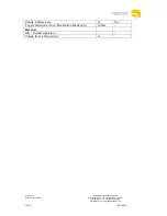
Page 12: ... device 7 1 Function Switch The function switch can be a simple momentary push button connected between pin J1 4 and ground or a transistor controlled by a micro controller Refer to the table below for exact timings required 7 1 1 Link When the button is pressed for a brief period of time the transmitter will link unlinked receivers within range 7 1 2 Unlink On a transmitter holding the button for...

Page 13: ...eparksvägen 7 451 55 Uddevalla Sweden 46 522 511 511 Tel 46 522 440 885 Fax Wirelessdmx com sales wirelessdmx com 13 23 14 11 2014 Unlink all Receivers 3s 10s Toggle direction at boot Flex Button Mode only 100ms Receiver Idle Normal Operation Unlink from a Transmitter 3s ...

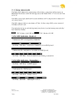
Page 14: ...stor The LED output can deliver a maximum of 15mA For the average LED a series resistor of 330ohms will work well The indications below are valid during steady state that is in normal running mode after the boot loader has finished Off denotes a dark LED and On denotes a lit LED 7 1 5 1 LED Indication Receiver 7 1 5 2 LED Indication Transmitter Continuously Off not assigned to a transmitter On 900...

Page 15: ... 6 Mode Indicator LED L6 only The Mode LED indicates whether the W DMX device is currently operating in G3 G4 G4S 2 4GHz or G4S 5 8GHz mode G4S 5 8 GHz mode on 500ms Off 500ms The LED is active high and should be connected between pin J1 9 and ground for example at pin J1 7 via a series resistor The LED output can deliver a maximum of 15mA For the average LED a series resistor of 330ohms will work...

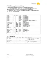
Page 16: ...the SPI output has ended 7 2 1 LED order Name Bit Text Color Description Signal 5 0 Green Signal strength Signal 4 1 Green Signal strength Signal 3 2 Green Signal strength Signal 2 3 Yellow Signal strength Signal 1 4 Red Signal strength G4 G4S indication on transmitter Transmit Mode 5 TX Green Radio transmitter Control Mode 6 CTRL Red In control mode Link 7 LINK Green Link established Data 8 DATA ...

Page 17: ... is performed configuration settings on the device is not affected and therefore the software lock that disable 2 4 functionality is not affected 8 1 Design considerations Designing for boot loader compatibility requires a few considerations that might not normally be included in a simple receiver setup 8 1 1 Bidirectional connection In a simple fixture external DMX ports might not be present For ...

Page 18: ...23 14 11 2014 9 Installation Guidelines The PCB is installed on the carrier board The box is opened by unscrew 4 screws from the bottom of the unit the screws is hidden by rubber feet s The electrical installation includes two parts Push out the plug for the antenna connector and then fasten the antenna cable in the chassis Connect the MCX connector on the antenna cable on the radiocard ...

Page 19: ... 11 2014 Connect the pin header on the radiocard to the carrier board and fixate with four screws To close the unit close the LID and fasten the 4 screws in the bottom put back the rubber feet Connect the antenna to the SMA connector on the box Finally when the installation is completed take the label Contains FCC ID NY2 WDMXTRXDB and fasten it on the product label on the bottom of the unit ...

Page 20: ...eding the values specified in the tables below will cause permanent damage and void any warranty 10 1Electrical Specifications Parameter Min Typ Max Unit DC Supply 5V DC input 4 9 5 0 5 1 V LED Pin output source current 20 mA DMX interface Maximum number of units on the DMX RS 485 bus As per the DMX Standard DMX data rate1 250 kbps ESD protection human body model None kV RF characteristics 5 8GHz ...

Page 21: ...arameter Min Typ Max Unit Ambient Operating Temperature 20 453 C Relative Humidity4 20 80 Option coated Relative Humidity4 20 95 1 Refer to Appendix 1 for Order Codes and a detailed description 2 Measured with no DMX on input output and no LEDs 3 Consult with Wireless Solution for temperatures exceeding 45 C 4 Non condensing Code1 Typ 2 mA Max2 mA Antenna Operating Mode Typ input power W Max input...

Page 22: ... 511 511 Tel 46 522 440 885 Fax Wirelessdmx com sales wirelessdmx com 22 23 14 11 2014 Appendix 1 Ordering Codes for Radio Cards Order Code Name Input Voltage Band GHz Direction Selector Ant RDM Notes WDMX TRX PRO G4 Transceiver MCX Connector DMX RDM 5 8GHz US Market only 5V 5 8 J1 4 MCX Yes Transceiver 5 8GHz only ...

Page 23: ...sion 4 Author Anders Zellén Wireless Solution Sweden Sales AB Stureparksvägen 7 451 55 Uddevalla Sweden 46 522 511 511 Tel 46 522 440 885 Fax Wirelessdmx com sales wirelessdmx com 23 23 14 11 2014 11 Notes ...

Reviews: