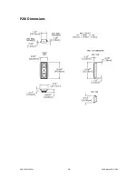
SAGE SERIES P20i
WISDOMAUDIO.COM
7
1.
Determine the area for the speaker installation and locate the cutout guide using
pushpins to secure it in place. Ensure that the template is plumb using a bubble
level or similar. Note: Make certain that there are no studs, plumbing or
electrical conduit in the intended area behind the wall before you begin marking
and cut- ting!
2.
Trace the outer perimeter of the cutout guide with a pencil or a utility knife.
3.
Remove the traced section of sheet rock using a keyhole saw, and clear debris
from the edge of the hole.
4.
Push any insulation to the side.
5.
Disassemble bezel/Uni- Grip™ and place the supplied Allen head screws to the
side. Place the bezel in the wall cutout and insert the Uni-Grip clamping bar
through the opening at an angle, working on one side first. Reinstall the Allen
head screws with the supplied 3/32" drill bit, securing both pieces to each other
(sandwiching the wall between them), but do not tighten yet. Repeat on the
other side.
6.
Using a level, adjust assembly in wall cutout to ensure that the assembly is
plumb. Tighten the Allen screws. Do not over torque or strip these screws. The
large clamping area of the Uni-Grip system does not require unusually high
torque on the screws to be secure.
7.
Paint the bezel and grill as necessary, being careful not to plug up the holes in
the grille. Note that the speaker modules are not mounted in the bezel and grille
assembly at this time. They can be mounted later, after all the paint is dry.
8.
Using assistance to hold the speaker modules away from the wall, connect both
high and low pass speaker cables to the two connectors at the ends of the back
boxes, paying attention to assign the correct band-pass and polarity to their
respective speaker connectors.
9.
Insert the speaker/back box assembly into the Uni-Grip frame and attach using
the supplied Allen head screws and 3/32" drill bit. Do not over torque or strip
these screws.


