9
6. Wiring
6.1 Detector wiring for GT-1010
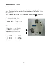
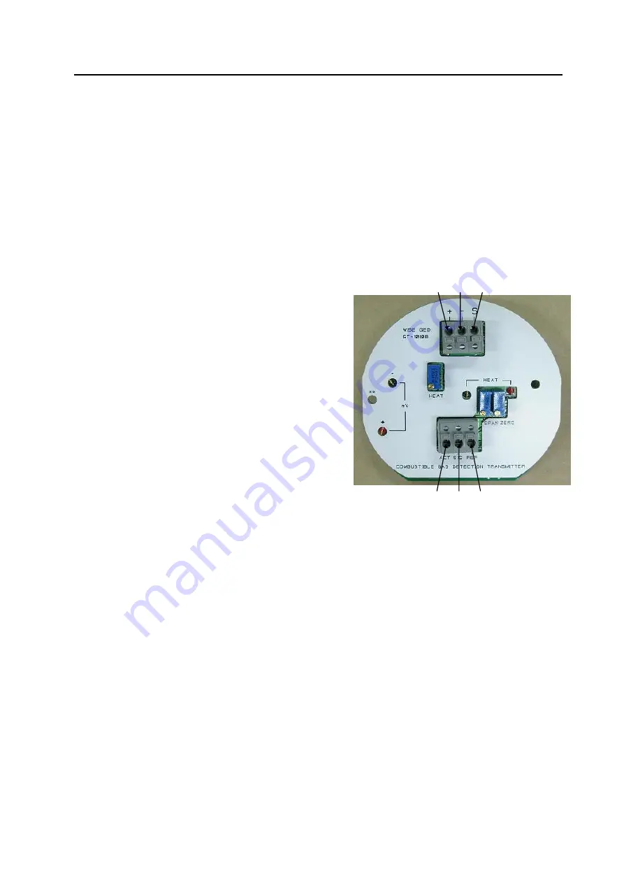
6.1.1. Power
After certify the power for using is the same as the power that designate in wiring diagram, you may wire.
In order to protect a surge, you may separate an instrument power and a power line (operation power of
heater, magnet S/W)
In order to protect a voltage drop by a wire resistance, you may use a wire has a large section area of
wire.
◎
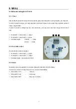
Terminal #1 : connect with ( + ) power
◎
Terminal #2 : connect with ( - ) power
◎
Permitted length :
1.25 SQ
→
1.8Km
2.5 SQ
→
3.0Km
6.1.2Transmitter output
One transmitter output is supplied.
◎
Terminal #2 : connect with ( - ) output
◎
Terminal #3 : connect with ( + ) output
◎
Permitted length : wire resistance 500
Ω
6.1.3Sensor
Generally, sensor is supplied for connected state with transmitter from the factory
In case of you have to change the sensor in your local Unavoidably
◎
Terminal #4 : ACT
→
red
wire
◎
Terminal #5 : SIG
→
white
wire
◎
Terminal #6 : REF
→
blue wire ( or black )
①
②
③
④
⑤
⑥


