7
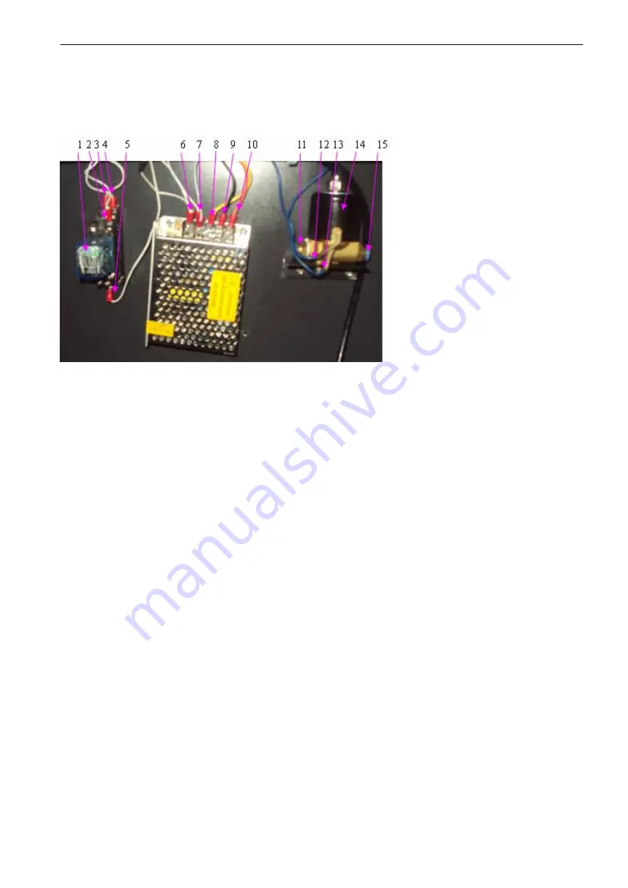
Sketch map of the solenoid valve
(
Optional device
)
z
1 DC24V relay
z
2 Pin 13 of the relay, connected with the control box 6535
z
3 Pin 12 of the reply, connected with the ground wire of the DC24V power supply;
z
4 Pin 14 of the reply, connect with the +24V of power supply DC24V;
z
5 Pin 8 of the reply, connect with the solenoid valve;
z
6 Ground wire of the power supply DC24V;
z
7 +V of the DC24V power supply;
z
8 The power supply of the DC24V;
z
9 Negative electrode of the DC24V power supply;
z
10 Positive pole of the DC24V power supply;
z
11 0utput of the solenoid valve;
z
12 Pin 8 of the reply
z
13 Connect with the positive pole of the DC24V power supply;
z
14 Solenoid valve;
z
15 Input of the solenoid valve;


