background image


19 

¾


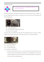
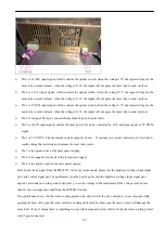
Second step: Stick a paper before the third reflecting mirror, press “Test light” on the panel, move the laser 

head back about 30cm, then the first and second reflecting mirror will be a little far, press “Test light” on 

the panel and check if the two dots are totally coincident. If not, please adjust the first reflecting mirror to 

make the dots coincident totally.   

¾


Third step: Move the laser head to the

 top left corner

 where the first and second reflector mirrors is nearest. 

Stick a paper before the third reflecting mirror, press “Test light” on the panel, Move the laser head back 

about 60cm, then the first and second reflecting mirror will be far, press “Test light” on the panel and check 

if the two dots are totally coincident. If not, please adjust the first reflecting mirror to make the dots 

coincident totally.   

¾


Fourth Step: Adjust the laser path as the second step and third step until the dots coincident totally. (Adjust 

the laser path at the distance between the first and the second reflecting mirror as 30cm, 60cm,90cm, 

120cm and so on.) 

4.3 Adjust the laser tube 

¾


After adjusting the mirrors, the laser dots are 

coincident totally. But maybe they are not in the center of the 

mirrors. The following steps are planning to make the dots in the center of the mirrors. 


¾


First step: Move the laser head to the

 top left corner

 where the first and second reflector mirrors is nearest. 

Put an acrylic, paper or other transparent non-metal before the third reflecting mirror, press “Test light” on 

the panel to make a laser dot on the material to check if the laser dot is in the center of the third reflecting 

mirror. If not, adjust the laser tube to make the laser dot in the center.   

¾


Second step: Move the laser head to the

 lower left corner

 where is most near the second reflecting mirror 

but most far from the laser tube to check if the laser dot is in the center of the third reflecting mirror. If not, 

adjust the laser tube to make the laser dot in the center. 

¾


Third step: Move the laser head to the

 top right corner

 where is most far from the second reflecting mirror 

but most near the laser tube to check if the laser dot is in the center of the third reflecting mirror. If not, 

adjust the laser tube to make the laser dot in the center. 

¾


Fourth step: Move the laser head to the

 lower right corner

 where is most far from the second reflecting 

mirror and the laser tube to check if the laser dot is in the center of the third reflecting mirror. If not, adjust 

the laser tube to make the laser dot in the center. 


Summary of Contents for MY-L6090

Page 1: ...ybe the machine is differing from the instruction If there is going to be some change we will tell you by attached sheet We regret any inconvenience Please contact our After sale service department if you need any help we will try our best to meet your requirement Because the I O laser power or laser tube is electrical please be more careful when you operate the machine to avoid electrical shock p...

Page 2: ...not point to themselves or others eyes even the case is closed there is the possibility on opening with an error 2 Laser is not a toy do not let children mental retardation and the people who do not understand laser characters to use in such cases easily lead to injury 3 The type of laser is not visible so prohibit to put flammable explosive materials near to the equipment to avoid deviation of la...

Page 3: ...t meter can not exceed 35mA 13 If there is some problems or cost fire please break off the power as soon as possible When meet suspicious problems please do not operate If there is some damage to this product please maintenance personnel to check it do not continue the operation Don t operate in the wet condition Don t operate it in the Explosion environment Keep the surface of machine body dry an...

Page 4: ...ne 5 2 Sketch map of the control system 6 Ⅲ The Installation of Laser machine 8 3 1 Unpack the package box 8 3 2 Positioning 8 3 3 Sketch map of the external laser power supply 9 3 4 Laser Tube structure and installation 9 3 5 Laser Power Supply installation 11 3 6 Water chiller installation 11 3 7 Installation of air compressor and air pump 13 3 8 Exhaust fan installation 15 3 9 Installation of t...

Page 5: ...parking from the exit of laser head 30 7 6 Water chiller alarming 30 7 7 X axis or Y axis does not move around or move abnormally 30 7 8 Laser head or beam shaking 31 7 9 Different engraving depth or could not engrave deep depth 31 7 10 Wrong engraving and not following the file engraving 32 7 11 Wrong size or not closing and malposition when its engraving 32 7 12 No output from the computer 32 7 ...

Page 6: ... It is manufactured by our company the key parts are imported components with the novelty appearance unique structure easy operation high modulation frequency fast speed high precision stable performance and so on The application scope of laser engraving machine is very wide Different designs have been used in machines of our company to meet the needs of all use We believe that the type of machine...

Page 7: ...ooling Model Water cooling Resolution 0 025mm Smallest Character Engraving Chinese 2mm English 1mm Accuracy of Repetition 0 01mm Voltage AC220V 5A 50Hz Total Power 2000W Supported Graphic Format BMP PLT DST AI DXF Drive Mode Stepper motor divided driving Laser Tube Power 120W Operation Temperature 0 45 Operation Humidity 5 95 ...

Page 8: ...ipped according to different machines being set up 2 2 System components This equipment is made up of five parts machinery platform optical system drive system control system and accessory system Machinery platform composed of fittings such as machine cover guide rail base frame reflector mount etc Optical system composed of laser tube laser power supply three reflecting mirrors and one focus head...

Page 9: ... X axis stepper motor z 7 Bulb socket z 8 Protect switch z 9 DC48V power supply which offers power to the drivers of the stepper motors z 10 DC24V power supply supply power for MPC6535 z 11 Driver of the Z axis stepper motor optional part z 12 Driver of the Y axis stepper motor z 13 Connecting wire of the laser tube z 14 Signal cable of the laser power supply ...

Page 10: ...V of power supply DC24V z 5 Pin 8 of the reply connect with the solenoid valve z 6 Ground wire of the power supply DC24V z 7 V of the DC24V power supply z 8 The power supply of the DC24V z 9 Negative electrode of the DC24V power supply z 10 Positive pole of the DC24V power supply z 11 0utput of the solenoid valve z 12 Pin 8 of the reply z 13 Connect with the positive pole of the DC24V power supply...

Page 11: ...see whether there is any scratch on the surface and the completeness of fittings 3 2 Positioning The machine should be put in cool and dry places It should be placed close to earth wire After the machine has been adjusted please don t move it again otherwise the ray path has to be readjusted After placing the machine please fix the six bottom wheels if the machine shaking please adjust the screws ...

Page 12: ...ube It is the most important part of the laser equipment because the laser device is sealed by the glass tube so it is called laser tube z Keep flat the machine when put it fixed well for every foundation the machine could not rocked or else will effect the engraving or cutting performance even damage to the machine or personal safety z The air humidity of the install place should not more than 50...

Page 13: ...er stable z The model of laser tube is usually decided by laser power the normal model is 15W 25W 40W 60W 80W 100W 120W 130W 150W z Laser tube with different laser power with different length such as 60w laser tube is 1200mm or 1 25mm 80w is 1600mm z Installation of the laser tube 1 The laser tube is glass material and fragile Remove the screws with the allen wrench in the toolbox put the laser tu...

Page 14: ... machine After one minute of water circulation please check out whether there is any bubble in the laser tube If there is please turn over the tube to push the bubble out z The cooling water could not frozen in cold regions especially after the machine stop working guarantee there is no cooling water within the laser tube to avoid the crack generated by cooling water frozen z Please note the drivi...

Page 15: ...input of the machine it connects with the air compressor 3 Inlet of the laser tube it connects with the outlet of the water chiller Water pump suggest to use water pump for the laser tube whose power under 40W z 1 Power line of the water pump z 2 Water pump z 3 Outlet of the water pump ...

Page 16: ...e water in the water chiller The water should be purified water or high purity water The temperature of the water in the chiller should be 15 30 If the temperature is too high please change the water or turn off the machine b The flow of water should be 2L 4L minute If too much or too little the laser dot quality and laser power will be affected The chiller should be full otherwise the tube can no...

Page 17: ... z 3 Power line of air compressor z 4 Air compressor z 5 Air outlet of air compressor z 6 Air filter z 7 Air outlet of air filter z 8 Filtering oil system z 9 Filter s air pressure adjusting knob z 10 Air pressure display clock of air filter z 11 Air inlet of air filter z 12 Filtering water system ...

Page 18: ...lation Connect the exhaust fan and machine with the air pipe Turn on the exhaust fan After a long time the exhaust fan will be polluted with dusts Please open the box of the exhaust fan remove the two pipes and then get rid of the dust in the fan z 1 Exhaust fan z 2 Wind outlet of exhaust fan z 3 Wind inlet of exhaust fan ...

Page 19: ...ctly When LaserCut51 LaserCut52 LaserCut53 is installed simultaneously please chose different disk such as D disk or E disk Ⅳ Structure and adjusting of laser path 4 1 Structure of the laser path Ray path is ray guide system The complete optical system is made up of laser tube three reflecting mirrors focus lens and relevant adjusting devices Ray path has close relationship with the effect of engr...

Page 20: ...left or right direction When the screw is tightened laser ray will move to the right direction z 5 Adjusting screw in the up down direction It can adjust the laser ray direction greatly Notice When tighten both 1 and 3 the laser path will move to left when tighten both 4 and 3 the laser path will create an upward moving 2 Sketch map of the guiding system z 1 Fix screw z 2 Adjusting screw z 3 Air t...

Page 21: ...e panel adjust the screws on the first reflecting mirror to make the laser in the center of the second reflecting mirror z 1 The second reflecting mirror z 2 The first reflecting mirror z 3 The outlet of the laser tube z 4 The green line is the laser path First step move the laser head to the top left corner where the first and second reflector mirrors is nearest Put an acrylic paper or other tran...

Page 22: ...are not in the center of the mirrors The following steps are planning to make the dots in the center of the mirrors First step Move the laser head to the top left corner where the first and second reflector mirrors is nearest Put an acrylic paper or other transparent non metal before the third reflecting mirror press Test light on the panel to make a laser dot on the material to check if the laser...

Page 23: ...it is not vertical adjust the mirror cover of the third reflecting mirror to make the ray vertical and thin Ray verticality adjusting is to adjust the ray position on focus lens Only the ray is in the center of focus lens can it be straight and strong Then adjust the focus distance Use the focus stick to adjust the focus distance Unscrew the lock cap and move the laser head to adjust the distance ...

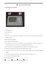
Page 24: ...ducing the cumulative error Ensure install the origin switch and input the switching signal into the control box 8 Pulse the laser tube will ray after pressed this button it is used for testing the light strong or weak 9 Stop press it when working the machine will stop working and return to origin 10 Test walk the frame the laser head doesn t ray just run quickly around the frame of the graph main...

Page 25: ...ng and returns to the original place Reset returned to the top right corner of the machine after pressed Pause stopped the laser head while working go on working after pressed Start The function on the panel is the same to the computer 5 2 Side sketch map z 1 Lamp switch z 2 Machine switch z 1 Red dot switch optional function z 2 USB port 5 3 How to turn on and turn off the laser machine a Turn on...

Page 26: ...ly caution 1 Please do not staring straight the laser beam 2 Operate the machine in the control area and add the signs of caution 3 People who have not been trained should not use the machine 4 Close the place around the laser path in case the laser escaped 5 Try to avoid the same height between the laser head and human eye 6 Pay attention to the ventilation and exhaust in the laser processing env...

Page 27: ...ng magnetism and so on 17 Power supply voltage the laser will work unstable because of the fluctuation for the input voltage if over tension the power system will be damaged forever So please install a power stabilizer at least 5000W to avoid damaged by the device circuit because of the voltage fluctuation and also guarantee the stability 18 Especially to the customer who is at the power instabili...

Page 28: ... cotton cloth and lubricant oil How to clean the rail push the laser head to one end of the rail and use the cotton cloth clean the rail after that add some lubricant oil on the different part of the rail and then push the laser head from one end of the rail to the opposite end make sure the oil can be symmetrical added on the rail 5 Tighten the screws and the shaft coupling After a period of the ...

Page 29: ...g key in the operator panel a No current check if the if the wires of the laser power supply high tension line and signal are connect well b Current is available Check if the mirrors or laser path is not correct c Check the water circulation system works well or not d Without water check the water chiller is electrified or damaged e With water check the water inlet and water outlet if connected in...

Page 30: ...imum current output is 20mA If connect one resistor between pin 5 and pin 6 could enlarge the electricity and increase the laser tube power Pin 7 is the ground wire of the laser power supply Pin 8 is the negative electrode of the laser power supply Pin 9 is the positive pole of the laser power supply First check if any signal from the PMC6535 when ray continuously please test the high level voltag...

Page 31: ... the laser tube to send out laser Pin 4 is P WP input signal which controls the optical switch when the voltage 3V the signal will agree the laser tube to send out laser when the voltage 0 3V the signal will not agree the laser tube to send out laser Pin 5 is G signal This pin connects the machine body and control card Pin 6 as the IN input signal controls the laser power It can be controlled by 0...

Page 32: ...e laser output switch c Adjust well for the gas well to ensure no flour adhesion it s better by side blown d Adopt the short focus Len consider the processing thickness while adjusting the Focus Len 7 4 Spots scattered not focusing lens cone heat phenomena of laser engraving machine 1 Fault phenomena the laser beam machining can see yellow and the rough beam diameter hollow spot when the hands tou...

Page 33: ... tube if it is bended or blocked whether the water protection is blocked Solving method clean or straighten the water tube or water protection 4 Check the water temperature see if it is much higher than the limited value Solving method change the water often or restart the machine to engrave after half an hour 5 Check the inner of water chiller and see is there anything wrong with the water output...

Page 34: ...lem is If there is any stoppage change another one in time 7 Reset in the right direction but in the end the laser beams can not stop or crash the machine So we need to check the parameters of motherboard whether sensor dust is excessive or not the sensor cable is disconnected or the sensor is damaged 8 If the problem still exists may be motherboard failure contact with the factory replacement mot...

Page 35: ...se adjust the synchronous belt if there is something wrong with it adjust the screw to suitable degree no double image for engraving letter and low noise while running the machine 5 Check the belt or synchronous belt is slip or Jumping over Teeth fasten the synchronous wheel or belt 6 Please check the beam is it parallel 7 Please check the pulley at the laser head is it abrade that s made the lase...

Page 36: ...in and then download the data 2 Hard limit stops When the user operate the machine while does not make the laser head back to the original point It is easy cause that the processing area is bigger than the real worktable and when the laser head bump into the size control signal the movement have to cease On the other hand when the machine in a complex environment which have a lot of interference s...

Page 37: ...g method a Please copy the new firmware file FM FMW and 05LM201 HDW two files to the root directory of U disk formatted as FAT16 we propose that U disk do not have any other files b Break off the power of MPC6515 35 insert U disk and then connect power for MPC6515 35 the light D1 on MPC6515 CPU main board flash 2 times fast and D1 is always on usually 2 to 5 seconds depending on the firmware firmw...

Page 38: ...t have a little b When you open set engraving parameters the parameters for different engraving speed can be seen the reverse gap is 0 you should adjust it as the matter of fact c You can chose single track light when best engraving effect needed Not to chose the draw of dual engrave but when you chose it the efficiency would be lower 6 The X axis or the Y axis not move MPC6535 a Stir knob to chos...

Page 39: ...in the guarantee period our company will provide service for problems that appear in normal using conditions for free This point is valid only for domestic customers Certain amount of maintenance fees will be charged by the company when offering service out of China 2 Certain amount of maintenance fees will be charged by the company when the guarantee period is over 3 Our company will not provide ...

Page 40: ... The manufacturer will not take any compensation responsibility for loss of commercial profits service interruption or any other monetary loss caused by the use or abnormal use of the product 7 This certificate will be valid only after being stamped by distributor It will be invalid if altered ...

Reviews: