27
¾
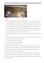
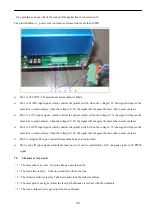
Pin 1 is H (TH) input signal, which controls the optical switch, when the voltage
≥
3V, the signal will agree the
laser tube to send out laser, when the voltage
≤
0.3V, the signal will not agree the laser tube to send out laser.
¾
Pin 2 is L (TL) input signal, which controls the optical switch, when the voltage
≥
3V, the signal will agree the
laser tube to send out laser, when the voltage
≤
0.3V, the signal will not agree the laser tube to send out laser.
¾
Pin 3 is P (WP) input signal, which controls the optical switch, when the voltage
≥
3V, the signal will agree the
laser tube to send out laser, when the voltage
≤
0.3V, the signal will not agree the laser tube to send out laser.
¾
Pin 4 is G signal. This pin connects the machine body and control card.
¾
Pin 5 is the IN input signal controls the laser power. It can be controlled by 0-5V analogue signal or 5V PWM
signal.
¾
Pin 1 is 5V VOUT. The maximum current output is 20mA. If connect one resistor between pin 5 and pin 6,
could enlarge the electricity and increase the laser tube power;
¾
Pin 7 is the ground wire of the laser power supply;
¾
Pin 8 is the negative electrode of the laser power supply
¾
Pin 9 is the positive pole of the laser power supply;
First, check if any signal from the PMC6535; when ray continuously, please test the high-level voltage input signal
pin 1 and control signal pin 3 by multimeter ( put the positive pole into the high-level voltage input signal pin 1,
negative electrode put on the ground wire pin 4), to see the voltage in the multimeter. If the voltage is much less
than 3V, then no signal provided from the MPC6535 board;
If no problem as above, test the water-cooling protect wire, short circuit the pin 3 and pin 4, to see if output while
opening the laser ( Do open the water chiller to cooling the laser tube when open the laser, or else will damage the
laser tube); if ray, it means there is something wrong with the signal in water chiller; check the water-cooling protect
wire if poor connected;


