background image

- 19 -

WISI LR 54 


Downstream

Upstream

Startdisplay

Menulevel 1 

Values

Opt.Trans-

mission Power

Up.ICS 

Pilot 

OT Laser 1

On / Off


On / off 

Menulevel 2 

V 1.0001

3...8%

1% Step

T:+47C 

Transmitter 

Opt. Transmission Power 

+3.0 dBm

2.0 mW

0,1...2 mW 0.1 mW Step 

ORP low

warn.

0,1...2 mW

0.1 mW Step 

ORP low

alarm

no, not save

yes, save

Save Val. >

OK41A

no, not save

yes, save

Rec. Val. <

OK41A

Low 0 dB

Pad 8 dB

High >45 dB

.

+ 0 dBm                                    

1 mW

Opt.

ALC Mode

Opt. ALC Mode

Optical ALC     on 

0...20 dB     0.5 dB Step

Out  slope


Out  

attenuator


opt. Rec

Atten.

(3) (ALC on/off schalten  

    ALC set to on/off)


Opt.Rec.Power

0...15 dB    0.5 dB Step

0...15 dB    0.5 dB Step

Enable Manu / auto Level

Spec.Lev.

Cntr.

(3)

(3)

-3 ...3 dB      1 dB Step

out.level

offs

ALC on

ALC off

Mit / 

with

 LT 4x

Opt.

RecPower

Sys.

Settings

Opt.

Mod.Index 

Summary of Contents for COMPACT LR 54 E2000

Page 1: ...es Personal ausgeführt werden Auf spannungsführende Teile achten Betriebs und Fernspeisespannung abschalten Optischer Empfänger Sender Integrierte Splice Box Rückwegtransmitter steckbar Diplexfilter Verteiler steckbar Interface für NMS Transponder Alle Einstellungen Pegel Slope etc mit WISI OK 41A Handset oder NMS bei Verwendung eines HMS Transponders Automatische Pegelregelung ALC über optische E...

Page 2: ...t Tx X oder LT 45 S 1510 nm opt Tx X oder LT 45 S 1530 nm opt Tx X oder LT 45 S 1550 nm opt Tx X oder LT 45 S 1570 nm opt Tx X oder LT 45 S 1590 nm opt Tx X oder LT 45 S 1610 nm opt Tx X 2 VT 51 transponder X 3 XE 50F Jumper X 4 XM splitter Jumper X Achtung XE 50F ist nicht kompatibel mit XE 50 Zubehör Handset OK 41A LR 54 S 230 VAC HF Ausgang 2 incl XM Splitter Breitbandiger Rückweg 0 300 MHz Kap...

Page 3: ...e Einstellungen wie Pegel Slope etc mit WISI OK41A Handset oder NMS falls ein HMS Transponder eingesetzt wird LED Anzeige für RX TX 24 V DC 5 V DC 8 V DC Optical Input Power Amp Testpoint 20 dB Out 1 Fuse µC Equalizer 0 15 dB Attenuator 0 15 dB AGC Handset interface Amp 230 V AC RX power Out 2 Pre Amp pigtailed PIN HP LP TX power Optical Output Amp Amp ICS OMI Control Return TX Module LT4x NMS DS ...

Page 4: ...uschen 5 pA Hz Summenstörabstände für CENELEC 42 Ch 110 dBµV flat 113 dBµV 9 dB slope CSO 60 dB CTB 60 dB HF Testpunkt 20 dB Upstream incl Sende Module Wellenlänge LT 40 S FP laser 1310 40 nm S SC APC LT 41 S 1310 20 nm LT 45 S 1430 1430 2 nm LT 45 S 1450 1450 2 nm LT 45 S 1470 1470 2 nm LT 45 S 1490 1490 2 nm LT 45 S 1510 1510 2 nm LT 45 S 1530 1530 2 nm LT 45 S 1550 1550 2 nm LT 45 S 1570 1570 2...

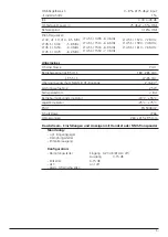
Page 5: ...eistungsaufnahme 25 W Fernspeisestrom 8 A Betriebsumgebungstemperatur 20 C 55 C Lagertemperatur 25 C 75 C EMV EN 50083 2 Schutzklasse IP 66 Abmessungen 260 x 215 x 95 mm Downstream Einstellungen und Anzeigen mit Handset oder NMS Transponder Monitoring opt Eingangspegel Dämpfungssteller Entzerrerausgang Konfiguration Dämpfungssteller Eingang 0 20 dB ALC off Ausgang 0 15 dB Entzerrer 0 15 dB ALC on ...

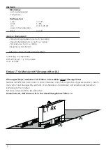
Page 6: ...sind einstellbar 1 abhängig vom Diplexfilter 2 EN 61000 4 5 1 2 50 µs pulse 3 nur bei HMS Führungsstifte A entfernen bei Einbau in Verstärker ohne Führungslöcher Module mit Stift A können dann in einen Verstärker ohne Führungslöcher eingesetzt werden indem man vorher die Führungsstifte entfernt LT 4x Module vom Verstärker und anderen elektronischen Komponenten fern halten Mit einer Zange die Stift...

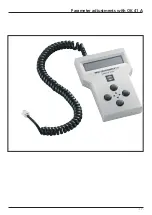
Page 7: ... 7 Parametereinstellung mit Handset OK 41A ...

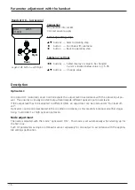
Page 8: ...angsleistung nach Dadurch wird ein nahezu konstanter Ausgangspegel bei verschiedenen optischen Empfangsleistungen erreicht Falls eine Anpassung des Ausgangspegels an unterschiedliche OMIs notwendig sein sollte kann unter Out level offset eine Anpassung vorgenommen werden Die optische ALC lässt sich im Auslieferungszustand nicht abschalten da so ein überfahren der einzelnen Verstärkerstufen bei hoh...

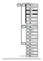
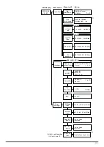
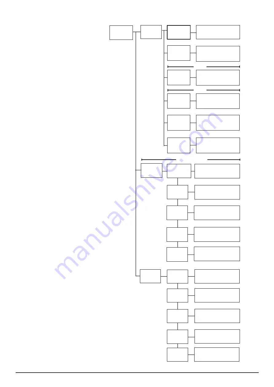
Page 9: ... Step ORP low alarm no not save yes save Save Val OK41A no not save yes save Rec Val OK41A Low 0 dB Pad 8 dB High 45 dB 0dBm 1 mW Opt ALC Mode Opt ALC Mode Optical ALC on 0 20 dB 0 5 dB Step Out slope Out attenuator opt Rec Atten 3 ALC on off schalten ALC set to on off Opt Rec Power 0 15 dB 0 5 dB Step 0 15 dB 0 5 dB Step Enable Manu auto Level Spec Lev Cntr 3 3 3 3 dB 1 dB Step out level offs ALC...

Page 10: ...cations GmbH Co KG Empfangs und Verteiltechnik Wilhelm Sihn Straße 5 7 75223 Niefern Öschelbronn Tel 07233 66 292 Fax 66 320 http www wisi de a link to the future Technische Änderungen und Druckfehler vorbehalten 03 08 ...

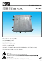
Page 11: ...rs plugable Interface for NMS transponder All settings level slope etc by WISI OK41A handset or NMS if a HMS transponder is used Automatic level control ALC for constant output level WISI COMPACT LINE EN 50 083 1ff Services and repairs should only be carried out by experts Pay attention to live parts or wires Switch off power supply or remote feed voltage LASER CLASS 1 Do not kink the optical fibr...

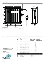
Page 12: ...x X or LT 45 S 1530 nm opt Tx X or LT 45 S 1550 nm opt Tx X or LT 45 S 1570 nm opt Tx X or LT 45 S 1590 nm opt Tx X or LT 45 S 1610 nm opt Tx X 2 VT 51 transponder X 3 XE 50F Jumper X 4 XM splitter Jumper X Dimensions Attention XE 50F is not compatible with XE 50 Accessory OK 41A handset LR 54 S 230 VAC 100 4 266 225 215 238 RF output 2 incl XM Splitter Broad band return path in 0 300 MHz remove c...

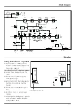
Page 13: ...or remote feed voltage 7 All settings level slope etc by WISI OK41A handset or NMS if a HMS transponder is used LED indicator for RX TX 24 V DC 5 V DC 8 V DC Optical Input Power Amp Testpoint 20 dB Out 1 Fuse µC Equalizer 0 15 dB Attenuator 0 15 dB AGC Handset interface Amp 230 V AC RX power Out 2 Pre Amp pigtailed PIN HP LP TX power Optical Output Amp Amp ICS OMI Control Return TX Module LT4x NMS...

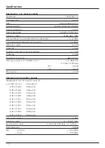
Page 14: ...0 5 dB Equivalent noise input 5 pA Hz Distorsion products for CENELEC 42 Ch 110 dBµV flat 113 dBµV 9 dB slope CSO 60 dB CTB 60 dB RF test point 20 dB Upstream incl transmitter module WavelengthLT 40 S FP laser 1310 40 nm S SC APC LT 41 S 1310 20 nm LT 45 S 1430 1430 2 nm LT 45 S 1450 1450 2 nm LT 45 S 1470 1470 2 nm LT 45 S 1490 1490 2 nm LT 45 S 1510 1510 2 nm LT 45 S 1530 1530 2 nm LT 45 S 1550 ...

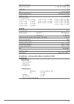
Page 15: ...ply RF inputs 2 6 kV2 Power consumption 25 W Remote power current 8 A Ambient temperature 20 C 55 C Storage temperature 25 C 75 C EMC EN 50083 2 Protection class IP 66 Dimensions 260 x 215 x 95 mm Downstream settings and reading via handset or NMS transponder Monitoring opt input level Attenuator Equalizer out Configuration Attenuator in0 20 dB ALC off out 0 15 dB Equalizer 0 15 dB ALC control on ...

Page 16: ...olds are variable When mounting the modules into an amplifier without sprocket holes first remove the gui ding pins A Modules having guiding pins A can be put into an amplifier without sprocket holes by removing the pins prior to mounting To do this please keep the LT 4x module in a safe distance from the ampli fier and other electronic equipment Cut off the pins A with a pliers Please make sure t...

Page 17: ... 17 Parameter adjustments with OK 41 A ...

Page 18: ...adjusts the output level in accordance with the optical input po wer This ensures a virtually constant output level despite different optical input power levels If the output level has to be adapted to different OMIs an adjustment can be made under Out level off set Optical ALC cannot be deactivated in the condition on delivery as this prevents individual amplifier stages being overridden at high ...

Page 19: ...W Step ORP low alarm no not save yes save Save Val OK41A no not save yes save Rec Val OK41A Low 0 dB Pad 8 dB High 45 dB 0dBm 1 mW Opt ALC Mode Opt ALC Mode Optical ALC on 0 20 dB 0 5 dB Step Out slope Out attenuator opt Rec Atten 3 ALC on off schalten ALC set to on off Opt Rec Power 0 15 dB 0 5 dB Step 0 15 dB 0 5 dB Step Enable Manu auto Level Spec Lev Cntr 3 3 3 3 dB 1 dB Step out level offs AL...

Page 20: ...erteiltechnik P O BOX 1220 75219 Niefern Oeschelbronn Germany Phone 49 7233 66 280 Fax 66 350 E mail export wisi de Internet http www wisi de a link to the future Technical Modifications reserved WISI cannot be held liable for any printing error 03 08 ...

Reviews: