background image


Instruction manual


Floodlight 5000 


21


 Ed. 2.01 

– 12/2019  


Article N

o

 50108013001 


Summary of Contents for Floodlight 5000

Page 1: ...Article No 50xxxxxx Ed 2 0 07 2019 P a g e 1 Keep the instruction manual always handy ...

Page 2: ...S 3 SAFETY INSTRUCTIONS 3 DESCRIPTION AND INTENDED USE 5 OPERATION 6 MALFUNCTIONS DURING OPERATION 6 CLEANING 6 REGULAR REVIEW 7 DISPOSAL AND DECOMMISSIONING 7 MOUNTING AND ASSEMBLY 8 COMMISSIONING 12 MAINTENANCE AND REPAIR 12 TECHNICAL DATA 16 ACCESSORIES SPARE PARTS 19 DECLARATION OF CONFORMITY CERTIFICATE 20 ...

Page 3: ... Icon Signal word Meaning DANGER Probable result Immediate death or serious injury WARNING Possible result death or serious injury CAUTION Possible result Slight to moderate injury to persons ATTENTION Possible consequences Material damage and malfunctions Electrician Installation and repairs may only be carried out by a qualified electrician electrical skilled person Electrical voltage Injury due...

Page 4: ...ARNING Never repair damaged power cables This poses danger to life Disconnect the Floodlight from the mains and have it repaired All cables and accessories must be professionally installed to function reliably Consider the national and local installation requirements and classification rules In some countries lighting may only be installed by registered installers Clamping screws in electrical con...

Page 5: ...version comes with a cable Optional protective grilles are available for the front glass panes The Floodlight 5000 is approved for outdoor use and meets the degrees of protection mentioned below 1 module IP66 68 2 4 modules IP66 67 Front view Rear view Illustration 1 Overview Floodlight 5000 2x40 Pos Designation 1 LED module 2 Case 3 Cover 4 Mounting bracket 5 Cable gland 6 Terminal box Floodlight...

Page 6: ...y connected Ask the electrician to check the connection Connection cable is defective Ask the electrician to replace the connection cable or LED module Water in the LED module Ventilation is defective Ask the electrician to replace the LED module Housing is broken Washer is leaking Incorrect illumination Floodlight suspension needs adjusting Realign the floodlight and retighten the screws One LED ...

Page 7: ...ht is switched on during maintenance work the light intensity can permanently damage the eyes People can become disoriented and fall down Before maintenance switch off the light and secure the product from being switched on again Disposal and decommissioning Comply with the local and national laws guidelines and regulations regarding the disposal of materials and products Waste Electrical and Elec...

Page 8: ... electric currents Working on open circuits can result in short circuits and body shorts An electrician should be present when working on electrical components Make sure that the system is disconnected from the electrical connection Secure the power supply against being switched on again Cover open external plant components If necessary short circuit the system components Test whether the system i...

Page 9: ... L2 160 mm L3 70 mm B 434mm Version 5000 4x40 L1 309 mm L2 249 mm H1 60 mm H2 35 mm B 437mm use only together with a mobile railing bracket 9 3 Installation Required tools Screwdriver open end wrench ratchet lever CAUTION Floodlight is heavy Injuries and damage from falling down are possible Use lifting gear if applicable and secure the floodlight using another person s help Mount the bracket on t...

Page 10: ...EFERENCE Make sure that a light switch is installed in the electrical supply line The electrical connection is only described for the versions 2x40 up to to 4x40 W The version 1x40 is supplied with 1 5 m connection cable Characteristic data Nominal voltage Nominal power Wire cross section Cable diameter 100 240V AC 50 60 Hz 1x40W to 4x40W corresponding to the number of modules Max 3x4mm2 max 3x AW...

Page 11: ...erminal blocks with push in connectors The tightening torque for the cable gland should be 4Nm Wire it up Use Phase L Neutral N and Protective Earth PE conductor Lay on the wires Close the terminal box Close the cover screws 3 4 7 For 2 3 modules For 4 modules Press down the dressing orange 8 Insert the cores 5 6 4x i ...

Page 12: ...ead to short circuits and body short circuits An electrician should be present when working on electrical components Make sure that the system is disconnected from the electrical connection Secure the power supply against being switched on again Cover open external plant components If necessary short circuit the system components Test whether the system is voltage free 11 1 Replacement of the modu...

Page 13: ...dlight and disconnect the connection cable before starting the maintenance process Remove the 6 front screws Keep the screws for installation Loosen the rear cover Remove cover Lifting the old module out of the frame Insert the new module Assemble the parts Replace the cover and fasten it Fasten the 6 screws Tightening torque 4 Nm 1 2 3 4 5 6 7 8 i ...

Page 14: ...floodlight from the power supply Observe safety measures to prevent reconnection Required tools Electric drill rivets screwdriver Drill out 4 rivets each to loosen the rear cover above and below the terminal box Remove the cover to loosen the cable gland Open the terminal box a Disconnect the wires b a Remove the front rivets Remove the module frame Pull the module out of the frame Insert the new ...

Page 15: ...dule floodlight Remove the outer and middle screws Position the protective grille on the floodlight Fasten it using the original screws Required tightening torque 3 Nm Mounting on a floodlight with multiple modules Place the grille over the frame and ensure the rivet holes are aligned Fastening the grill using the supplied rivets 1 2 1 2 2 3 3 i ...

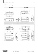
Page 16: ...e of protection One module IP66 68 Multiple modules IP66 67 Protection class SK I protective conductor 12 1 Dimensions mm Version Outer dimensions Mounting bracket Weight W H D L W H mm mm mm mm mm mm kg 5000 1x40 405 155 115 405 50 120 4 3 5000 2x40 434 269 148 434 50 185 9 2 5000 3x40 434 397 148 434 50 185 12 5 5000 4x40 437 509 148 437 60 305 16 4 Including the mounting bracket Without the pro...

Page 17: ...Instruction manual Floodlight 5000 17 Ed 2 01 12 2019 Article No 50108013001 12 2 Dimensional drawings 5000 1x40W 5000 2x40W 5000 3x40W 5000 4x40W ...

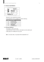
Page 18: ...lowing Pos Designation 1 Article short text 2 Performance data 3 Power consumption 4 Country of origin 5 Serial number 6 Notified Body 7 Identification index 12 4 Scope of delivery The floodlight is mainly custom made It optionally features a narrow medium or wide beam lens and a protective grid Further options are available based on the order Note A connection cable is only provided with Floodlig...

Page 19: ...e single variant 22000984 4 2 Mounting bracket for the double triple variants 22000998 4 3 Mounting bracket for the fourfold variant 22000985 5 Cover 5 1 Cover for the single variant 22000991 5 2 Cover for the multiple variants 22001131 6 Junction box 6 1 Junction box for the double variant 22000995 6 2 Junction box for the triple variant 22000996 6 3 Junction box for the fourfold variant 22000997...

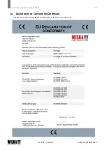
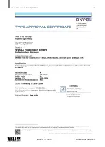
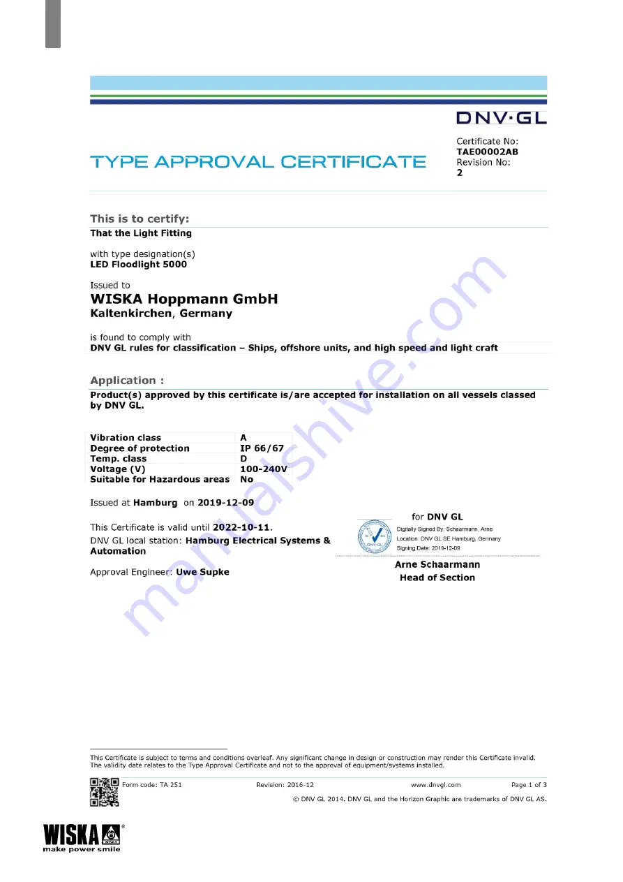
Page 20: ...Instruction manual Floodlight 5000 20 Ed 2 01 12 2019 Article No 50108013001 Declaration of Conformity Certificate The declaration of conformity for each floodlight can be found on www wiska com ...

Page 21: ...Instruction manual Floodlight 5000 21 Ed 2 01 12 2019 Article No 50108013001 ...

Page 22: ...Instruction manual Floodlight 5000 22 Ed 2 01 12 2019 Article No 50108013001 ...

Page 23: ...Instruction manual Floodlight 5000 23 Ed 2 01 12 2019 Article No 50108013001 ...

Page 24: ...ORIGINAL Subject to change without notice WISKA Hoppmann GmbH Kisdorfer Weg 28 24568 Kaltenkirchen Germany Phone 49 0 4191 508 0 Fax 49 0 4191 508 249 contact wiska de www wiska com ...

Reviews: